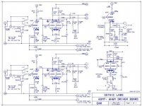
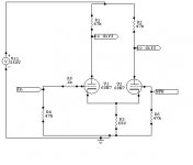
I'm building a ST70 clone with Hammond 6.6k OPT's with the original board to start. I wanted to upgrade it towards a more optimum amp. The 6.6k gives a little less power but a little larger class A operation. I've been reading the posts and will try to make a universal board for experimenting with 6SN7's for input and 6H6n for the differential phase splitter.
Bias is of concern, from the posts the 6SN7 likes a little current, is 4.2ma adequate or is it starved, and 6ma through the 6h6n differential?? I can put a bipolar current limiting scheme on the diff pair if there is a sonic reason for doing so. I've added different biasing ideas for the 6SN7 , and input bandwidth limiting filter 7 to 44k should I ever want to stifle the source a little. The transformer is stout so I can increase the B+ to either circuits up to about 450V. KT88's have been chosen for outputs, but I have a set of EL34's as well. Just starting the wood work, I'm finding myself challenged in this area. Hopefully the PCB for the power supply will go easier.
Please review and advise.....
Attachments
I have no knowledge about ST70s, but what the heck. Looks pretty ok to me, tho just skimmed at it. All the filtering I don't like, (the BW limiting stuff), but we are all different😉
The 25kohm resistor on the tail of the diff stage is pretty high in resistance, not sure you'll notice a sonic difference between that and a CCS. Other opinions?
It seems to me u want to direct couple the input stage to the phase splitter. The connection to the second triode of the phasesplitter pair has that RC thing. Howbout using two triodes in the input stage, with identical anode Rs and DC couple the phase splitter that way. You wont get much more phasesplitting from the input, but perhaps better (direct) coupling and PSRR.
Something like this:
Attachments
Last edited:
The input circuit would need a make before break switch, to ensure that the input grid is not left floating as you switch. Or put a 1M from the grid to ground, then you could add a capacitor to keep DC away from the pot. As it stands, you will have a change in resistance between the two settings which could cause a small change in bias.
The zener in series with the CCS will generate noise, although it will be attenuated by being common-mode into a differential stage. Why not use high-voltage transistors for the CCS? Your arrangement might work in a simulator, but as the valves age you will have to keep adjusting things.
In your original design R500 adjusts both bias and feedback. You need to separate these two functions, as in the alternative design. Be careful about how you arrange things at the input cathode. This affects LF stability and distortion. Better to have any electrolytic inside the feedback loop, not part of the feedback potential divider - so put the decoupled part next to the cathode, or omit the electrolytic.
Looks pretty similar to my design, which is just a re-hashed Mullard 5-20. I also used the 6n6p in the driver stage. It was tricky to get the right sized plate resistors in the driver stage, balancing the power supply availability with highest possible current through the triodes. I would say 6 mA per 6n6p is not ideal (they like more current) but the sonics of this amp are very pleasing.
For best results you WANT to put the CCS in the tail. Set it and forget it. Also, buy a batch of plate resistors and match them for balance with your meter. I ran a bunch of current through them, got them hot for a few hours before measuring. If you can get these resistors matched and have a well-designed CCS in the tail, your balance will be essentially perfect. Your limitation will be the ability of the diff-pair to drive the output stage at high frequencies, hence the desire for a low Rp tube and low R plate resistors. The cascode DN2540 CCS is a solid and ultra-simple design.
Recommend direct coupling the input and driver stages, since you have flexibility on your B+ you can tailor the driver as necessary. The SN7 will be a fine choice, but will limit the open loop gain of the amp. For that reason I went with the mu=60 12AT7. Gives you the ability to add a little NFB and still have a reasonably sensitive amp.
One issue I had after building was that the filter caps C4-C7 had to be increased to reduce bounce of the output. IIRC C5 and C7 ended up at 100 uF electrolytics, which was kind of a bummer. Everything else in the amp up to that point was PP film.
The input filter to remove bass is a very good idea; I installed an 87 Hz filter since I use a separate sub. The 44k filter is not a bad idea either, but maybe that could be increased a little. The goal is not to "stifle the source", but to limit the amount of high frequency energy that the amp has to deal with.
I found better sound with the switch in triode mode as opposed to ultralinear, but that will partially depend on your speakers. To simplify construction, next time I would remove the switch and strictly run triode.
I haven't found successful results with the feedback cap from UL tap to input cathode; best solution IMO is the RC network across the input stage plate resistor. Easy to set with a square wave and scope, and the scope results agree with the ear.
Attachments
CCS for phase driver stage
Thanks for everyone's input. I found a NPN 250 volt to remove the zener from the CCS, good idea! I did not think of noise being a possible issue. The 2n5655 will fit in the board. I also added 470K on the input to tame it when switching modes while hot, it could happen. I wanted the BW filter for turntable rumble, the old B&O still works and does a great job, but some old vinyl.... also did not want to over drive the transformers where they could not go.
Rebiased the 6sn7 to 9ma and differential stage to 10ma on the tail, to up it just change the resistor. Was able to fit in the 1k grid stoppers on the 6h6n that I left out... a doh moment.. I have a party pack of 6SN7's and Russian 6h6n's to use, thus the board. 12SN7's could also be used.
I did another board based on the compactron 6U10, triple triode tube. But from posts, it would work but not be the best sonic medium.. One strong recommendation was dual 7193 mickey mouse tubes instead of the 6SN7. I could not fit it in to the constraints of the board, 2 tubes instead of the one ,,,, but I could make it a little wider and take out the BW filter... If I cant sleep there could be another board designed..
Thanks again all, This is my first tube project, back ground was solid state designs, SO many tubes, SO little time...
Attachments
Back in about 1977 I "updated" my Eico HF-87 with a 6SN7 differential phase splitter that used a cheesy transistor/zener setup. But it worked, and pretty well at that. I think the plate current was about 8ma/triode. The hand-scratched schematic is from a time when ECAD wasn't generally available...
Jim
Jim
An externally hosted image should be here but it was not working when we last tested it.
Last edited:
Do you still listen to that amp Jim? If not, can I ask what type of amp you listen to these days? Just asking since you were doing things like that 30+ years ago, it would be interesting to hear which directions you went after that. Well, transistors were all the go then in 1977, people might have thought you to be a little backward by continuing with tube amps, is that right, or way wrong 😉
Actually, that was a mod that was pretty popular then- Ike Eisenson promoted the ideas of LED bias, CCS loading, and sold replacement boards for Dynaco amps using a CCS diff amp from his Audio Dimensions company.
Sy says: "that was a mod that was pretty popular then" - I actually designed that mod myself as I wasn't aware of prior work that I could have "referenced". 😉 Not to drag the thread too far off topic (but since you asked), I have a web page up on the amp that needs updating to the newest incarnation - mostly back to the stock topology with good parts, and here's the forum thread on stabilizing the amp. I'll update the web page and post schematics I'll as soon as I sort out the diode commutation noise and driver symmetry.
Oh, and the amp sits next to a Audio Research D90 and under a pair of Quicksilver monoblocks (and near a new but mostly unused Adcom GFA-555se) and holds its own very well. I've never had a transistor amp that thrilled me.
Jim
Oh, and the amp sits next to a Audio Research D90 and under a pair of Quicksilver monoblocks (and near a new but mostly unused Adcom GFA-555se) and holds its own very well. I've never had a transistor amp that thrilled me.
Jim
The unbalanced plate resistors are unnecessary. The imbalance is very roughly Rtail * Gm, which is about 1%. Use equal 5% resistors and call it even.
Tim
Tim
Tim, Assuming you are referring to the 47k//39k note on my schematic, it just means that I paralleled two resistors. The plate resistance is the same on each side.
Jim
Jim
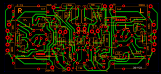
CCS in the LTP
Push come to shove, had to remove the input filter to get it all to fit without cramming it all in tooo tight. I put the CCS in for the LTP, it seamed the logical thing to do. I had to re-layout the PCB to allow heatsinks to fit. It turned out a little larger than the ST70 PCB. It includes input stage gain/bias adjustment, 2nd stage CCS bias adjustment and balance adjustment for the bias to the output tubes. It uses the Russian 6n6p ( 6H6pi) for the LTP and 6SN7 for the input stage. I thought with the heavy discussion on the different vintages and manufactures of the 6SN7, I would be able to roll tubes and find the correct characteristic to compliment the room dynamics.
Push come to shove, had to remove the input filter to get it all to fit without cramming it all in tooo tight. I put the CCS in for the LTP, it seamed the logical thing to do. I had to re-layout the PCB to allow heatsinks to fit. It turned out a little larger than the ST70 PCB. It includes input stage gain/bias adjustment, 2nd stage CCS bias adjustment and balance adjustment for the bias to the output tubes. It uses the Russian 6n6p ( 6H6pi) for the LTP and 6SN7 for the input stage. I thought with the heavy discussion on the different vintages and manufactures of the 6SN7, I would be able to roll tubes and find the correct characteristic to compliment the room dynamics.
Attachments
- Status
- Not open for further replies.
- Home
- Amplifiers
- Tubes / Valves
- CCS in Differential phase splitter?