Geek said:But the pads for R1 can arc if they're too close.
What sort of voltage will these things be running at? I might need to check a couple of other clearances.
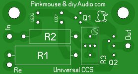
GeWa said:Well, this is the smallest I can get It without putting R1 and R2 upright.
(20mm x 37mm)
You can make it smaller removing both LEDs (Vbe of one cheap low voltage transistor is enough for reference voltage source, it will sense voltage drop on connected to the emitter of HV transistor resistor, and regulate it's base bias)
Wavebourn said:You can make it smaller removing both LEDs (Vbe of one cheap low voltage transistor is enough for reference voltage source, it will sense voltage drop on connected to the emitter of HV transistor resistor, and regulate it's base bias)
Not something we want to do... this is a Morgan Jones circuit design...
dave
That's cheating!
Putting the resistors in the upright position to! 🙂
Planet10 adviced not to do this (safety).
Regards
GeWa said:Planet10 adviced not to do this (safety).
He told me to do it to make the board smaller! 🙂
Planet10 adviced not to do this (safety).
Advised is maybe to strong a word, I only acted on his respons in post #167.
Regards
GeWa said:Putting the resistors in the upright position
I did indeed suggest it to PM... if they are we do have to be careful with the sticky up ends... perhaps a bit of heatshrink would fix that if the positioning of the board might cause an accident.
We are exploring options and potential issues with those options, weighing plus & minus.
I really like how this has been going.
I am all for small, the 1 in^2 of PM's latest is real appealing -- small enuff to maybe give the option of hanging it off the tube socket.
dave
pinkmouse said:
That's cheating! 😉
No, just optimizing. You use LEDs as a reference voltage source, but you have already B-E voltage reference. However, if some other specs such as Guru names and Bible dogmas are more significant than technical criteria, I'm out... I am not religious, I am just an engineer... 😉
The LED has a lower dynamic impedance and a higher reference voltage (which forces the output Z to be higher).
SY said:The LED has a lower dynamic impedance and a higher reference voltage (which forces the output Z to be higher).
In my case you may divide dynamic resistance of BE by beta of the same transistor. Let's compare output Z in both cases. 😉
OK, let's.
For the sake of discussion, we'll construct a 10mA high voltage CCS with a BC549 on the bottom and an MJE340 on the top. For a 1.7V reference, the emitter resistor will then be 100 ohms. The output Z has two terms, the dominant one being hte product of the two hfes and the resistor. For typical units, that would be 300x50x100 = 1.5M. Added to this will be 1/hoe of the MJE340, but that will be pretty negligible (it's something like 50k, if my memory serves). So, let's call the total 1.5M.
Your turn.
SY said:OK, let's.
For the sake of discussion, we'll construct a 10mA high voltage CCS with a BC549 on the bottom and an MJE340 on the top. For a 1.7V reference, the emitter resistor will then be 100 ohms. The output Z has two terms, the dominant one being hte product of the two hfes and the resistor. For typical units, that would be 300x50x100 = 1.5M. Added to this will be 1/hoe of the MJE340, but that will be pretty negligible (it's something like 50k, if my memory serves). So, let's call the total 1.5M.
Your turn.
You forgot about dynamic resistance of your LEDs and current variations supplied by a resistor in series with them and by bases of transistors.
I'll take the same BC549 and MJE340.
Base of MJE340 goes to collector of BC549, emitter of MJE340 goes to base of BC549. Emitter resistor of MJE340 will be 51 Ohm. The sum of base and collector currents flows through this resistor minus base current of the BC549, so dynamic resistance will be product of them and dynamic resistance of the B-E junction of the BC549 and of both H21. It is not straightforward to calculate, so I propose to simulate both variants with software (I don't have one). It will be roughly dV/dI where dV will be voltage variations that are determined by an input resistance of BE, i.e. very small, much less than 0.5V on the base, dI will be current variations on the resistor.
Dynamic resistance is about 4R5. I suspect that's low enough.😉 The worst-case variation in current because of base draw will be something like 10mA/hfe2, or 0.03mA.
From your description, you're talking about ring-of-two? I've tried them, they seem to work fine, but I sometimes had problems with oscillation. The cascode has worked perfectly every time.
From your description, you're talking about ring-of-two? I've tried them, they seem to work fine, but I sometimes had problems with oscillation. The cascode has worked perfectly every time.
SY said:Dynamic resistance is about 4R5. I suspect that's low enough.😉 The worst-case variation in current because of base draw will be something like 10mA/hfe2, or 0.03mA.
From your description, you're talking about ring-of-two? I've tried them, they seem to work fine, but I sometimes had problems with oscillation. The cascode has worked perfectly every time.
You could spend 1 resistor to stop oscillations (i.e. make dynamic resistance less) instead of 2 LEDs in case of cascode. However, if LEDs are free, and they look nice, ... 😉
Pentodes loaded by CCS will oscillate on low voltages because of the 2'nd emission that causes a negative dynamic resistance.
Well, you can certainly float a design out there, build several versions, document it, have it replicated, and we can do a performance comparison. Though I'd argue that we've already hit the diminishing returns point.
pinkmouse said:
What sort of voltage will these things be running at? I might need to check a couple of other clearances.
Higest I have had them so far is 400V across a 2W resistor. I generally keep them at no greater than 350V though. Running them off the main B+ is great to avoid a second supply.

- Status
- Not open for further replies.
- Home
- Amplifiers
- Tubes / Valves
- CCS for tubes/valves: PCBs