The following shall show a means to reduce the effects of shoot-through and body diode-conduction (i.e. reverse-recovery). It will not be a cure-all, but it can give relief to these effects. It works best when the deadtime is around zero. But it is not restricted to zero deadtime. It can actually work from negative to positive deadtime. It can reduce the demands on accuracy of deadtime setting. It does not control the deadtime itself by any means - but it helps to reduce the effects of deadtime tolerances. I have to admit that adaptive deadtime-control would be superior to this but I think that this only makes sense for highly integrated solutions (there are many interesting patents on that subject BTW).
I searched intensively in order to find out if it is already patented (and stumbled over a lot of interesting things while doing so) but didn’t find anything. So it is herewith released to the public domain unless proven otherwise. Feel free to use it. If you use it commercially however, don’t forget to mention its origin! You are of course free to post your experiences with it here.
The idea actually came from some tinkering around adaptive deadtime control. I was thinking about using a small transformer in order to measure cross-conduction. I then remembered that there was an output stage topology by Brian Attwood (Used in the Peavey DECA series of amps), that uses inductors to reduce cross-conduction since he isn’t a fan of deadtime. He also proposed some autotransformer topology to reduce body-diode conduction (I.e. the output inductor was used as auto-transformer). I once tried the latter and it actually works - but it only works well with output coils that have many turns.
Since body diode conduction isn’t that much of a problem with short deadtime - I didn’t actually care for it with the proposed circuit but it seems to be intrinsically taken care of by the circuit as well to some degree.
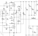
So here we have it. It is a small autotransformer with very low inductance (<1uH). Both legs are going to the switching devices and the centre tap is connected to the output-filter coil. There are two additional fast-recovery diodes needed as well.
And now have fun !
I searched intensively in order to find out if it is already patented (and stumbled over a lot of interesting things while doing so) but didn’t find anything. So it is herewith released to the public domain unless proven otherwise. Feel free to use it. If you use it commercially however, don’t forget to mention its origin! You are of course free to post your experiences with it here.
The idea actually came from some tinkering around adaptive deadtime control. I was thinking about using a small transformer in order to measure cross-conduction. I then remembered that there was an output stage topology by Brian Attwood (Used in the Peavey DECA series of amps), that uses inductors to reduce cross-conduction since he isn’t a fan of deadtime. He also proposed some autotransformer topology to reduce body-diode conduction (I.e. the output inductor was used as auto-transformer). I once tried the latter and it actually works - but it only works well with output coils that have many turns.
Since body diode conduction isn’t that much of a problem with short deadtime - I didn’t actually care for it with the proposed circuit but it seems to be intrinsically taken care of by the circuit as well to some degree.
So here we have it. It is a small autotransformer with very low inductance (<1uH). Both legs are going to the switching devices and the centre tap is connected to the output-filter coil. There are two additional fast-recovery diodes needed as well.
And now have fun !
Attachments

phase_accurate said:The following shall show a means to reduce the effects of shoot-through and body diode-conduction (i.e. reverse-recovery). It will not be a cure-all, but it can give relief to these effects. It works best when the deadtime is around zero. But it is not restricted to zero deadtime. It can actually work from negative to positive deadtime. It can reduce the demands on accuracy of deadtime setting. It does not control the deadtime itself by any means - but it helps to reduce the effects of deadtime tolerances. I have to admit that adaptive deadtime-control would be superior to this but I think that this only makes sense for highly integrated solutions (there are many interesting patents on that subject BTW).
I searched intensively in order to find out if it is already patented (and stumbled over a lot of interesting things while doing so) but didn’t find anything. So it is herewith released to the public domain unless proven otherwise. Feel free to use it. If you use it commercially however, don’t forget to mention its origin! You are of course free to post your experiences with it here.
The idea actually came from some tinkering around adaptive deadtime control. I was thinking about using a small transformer in order to measure cross-conduction. I then remembered that there was an output stage topology by Brian Attwood (Used in the Peavey DECA series of amps), that uses inductors to reduce cross-conduction since he isn’t a fan of deadtime. He also proposed some autotransformer topology to reduce body-diode conduction (I.e. the output inductor was used as auto-transformer). I once tried the latter and it actually works - but it only works well with output coils that have many turns.
Since body diode conduction isn’t that much of a problem with short deadtime - I didn’t actually care for it with the proposed circuit but it seems to be intrinsically taken care of by the circuit as well to some degree.
So here we have it. It is a small autotransformer with very low inductance (<1uH). Both legs are going to the switching devices and the centre tap is connected to the output-filter coil. There are two additional fast-recovery diodes needed as well.
And now have fun !
The same scheme is used by Crest Audio intheir LT series Class-D amps with auto transformer inductance beiing 200-300nH, and its already patented by peavey.
Hello Charles, your idea is similar this BCA technology (imho)...am i wrong? can't see any difference 🙁
Hi Kanwar
The topology in the Peavey patent OUTPUT INDUCTOR in an autotransformer fashion. And then there are additional magnetic snubbers (not coupled in any fashion). The original topology used a total of 6 additional components. While Crest only uses four additional ones (RC snubbers not counted).
But none of them uses the snubbers in a coupled (i.e. autotransformer) fashion (my topology uses only tree additional components BTW).
I think it is distinct enough for not being covered by the Peavey patent. There might however exist a patent that describes exactly that but I havent seen any so far. But I must admit that I have only searched class-d audio patents and not DC choppers for motion control, PSUs etc etc.
Regards
Charles
The main drawback of this classic arrangement is that both the switches, the diodes and the inductors have to carry maximum switch current (output current plus reverse recovery peak) during most of the time because there is no quick way to de-energize the inductors. Another drawback is that hard switching is still taking place on the axiliary diodes.
Eva said:The main drawback of this classic arrangement is that both the switches, the diodes and the inductors have to carry maximum switch current (output current plus reverse recovery peak) during most of the time because there is no quick way to de-energize the inductors. Another drawback is that hard switching is still taking place on the axiliary diodes.
But does it keep the current out of the slow MOS body diodes? (I don't think so)
If it does then the hard switching of the auxiliary diodes isn't such a problem, there are some very fast soft recovery diodes available.
If it doesn't then the switching losses might go up compared to a normal circuit.
Ian
But does it keep the current out of the slow MOS body diodes? (I don't think so)
It does so by not needing deadtime. Body diodes usually get into conduction during deadtime.
If it does then the hard switching of the auxiliary diodes isn't such a problem, there are some very fast soft recovery diodes available.
Exactly !
Regards
Charles
Hi, EVA,
Do you have any special trick to make body dioda Qrr (of an off-state mosfet) not shoting-through (crossconduction) to the other side mosfet when that particular mosfet is off?
Do you have any special trick to make body dioda Qrr (of an off-state mosfet) not shoting-through (crossconduction) to the other side mosfet when that particular mosfet is off?
Yes, I have developed a new system based in my old magnetic snubber that achieves controlled di/dt and no cross-conduction losses during reverse recovery without additional conduction losses, but I can't release the details to the public domain because I'm using it in commercial projects. I'm currently finding out how it blends with self oscillating class D and 420V supply...
phase_accurate said:
It does so by not needing deadtime. Body diodes usually get into conduction during deadtime.
Exactly !
Regards
Charles
True so long as MOSFET Ron is low enough that the body diode doesn't turn on anyway when current is being forced backwards into the output by the filter inductor, which is not easy to guarantee.
The problem comes at high temperatures where Ron goes up, the body diode forward voltage drops, then at high peak currents the nice slow body diode turns on and *bang* one ex-amplifier...
Ian
The problem comes at high temperatures where Ron goes up, the body diode forward voltage drops, then at high peak currents the nice slow body diode turns on and *bang* one ex-amplifier...
Agreed - but
1.) how do those amps cope with this that don't have any fast freewheeling diodes and that just rely on precise timing ?
2.) Would the freewheling current be distributed to both, the MOSFET and the additional fast-recovery diode (the latter's forward voltage migt also drop with temperature, thermal coupling might possibly be of advantage here).
3.) Would the peak current due to reverse-recovery also be limited by my circuit.
I didn't test this circuit in practice but simulations looked really promising.
Regards
Charles
phase_accurate said:
I didn't test this circuit in practice but simulations looked really promising.
Hi Charles,
Sims may be promising, but real world has got something else.
Crest discontinued their LT series which were using same scheme as your's and launched CD series containing series schottky+fred solution. 😉
One more possible solution is to use fast IGBT from IXYS C2DI series, i have used them without a problem, they also contain a 30nS fred integerated with it.
It's almost imposible to give accurate advice on this topic if you have never put together a few SMPS and class D prototypes with different topologies and you have never played with them and an oscilloscope for some time... 😉
There are some details about real circuit behaviour that may seem counter-intuitive at first. I encourage everybody to build prototypes. For example, it's not that hard to produce reliable circuits with nearly no dead time. MOSFET turn-on and turn-off in real circuits exhibits some kind of smart bahaviour 😀
At 200 volts or below and with the proper choice of MOSFET model and amount, layout, driver circuit, etc.., it's not that hard to achieve ridiculously small switching losses. Above 200 volts these tricks are also valid but become a bit expensive and bulky. Fortunately, coils and hyperfast diodes are of great help when it comes to switch 400V on body diodes with very little losses. I'm sorry but I can't give more details.
Eva said:It's almost imposible to give accurate advice on this topic if you have never put together a few SMPS and class D prototypes with different topologies and you have never played with them and an oscilloscope for some time... 😉
There are some details about real circuit behaviour that may seem counter-intuitive at first. I encourage everybody to build prototypes. For example, it's not that hard to produce reliable circuits with nearly no dead time. MOSFET turn-on and turn-off in real circuits exhibits some kind of smart bahaviour 😀
At 200 volts or below and with the proper choice of MOSFET model and amount, layout, driver circuit, etc.., it's not that hard to achieve ridiculously small switching losses. Above 200 volts these tricks are also valid but become a bit expensive and bulky. Fortunately, coils and hyperfast diodes are of great help when it comes to switch 400V on body diodes with very little losses. I'm sorry but I can't give more details.
Eva, my curiosity is piqued here -- once they've turned on, the only way I can see to losslessly remove charge from slow body diodes is to pull current the other way though an inductor (otherwise power loss is massive) by turning the opposing MOSFET on early i.e. deliberate overlap. Then when you turn the switching MOSFET off the current is flowing forwards not through the reverse diode, so no reverse recovery loss.
But for this to work the overlap-generated current must be considerably bigger than the largest possible peak output current to make sure the diode turns off before the MOSFET. This means that the switching current is more than doubled, so power loss for a MOSFET is more than quadrupled during this time (several hundred ns for the slow body diode in a superjunction MOSFET). And then you have to get the stored energy back out of the inductor somehow...
Which means you've traded switching loss due to diode reverse recovery for higher switching loss due to increased current during the transition -- this may or may not be an improvement depending on trr of the diodes vs. risetime.
However you then have the same problem as resonant SMPS in overload -- if the output current exceeds the designed maximum (due to low impedance load) then the diodes turn on, and it's bye-bye amplifier (smoke) as switching dissipation goes through the roof :-(
Unless you've come up with the Holy Grail of class-D design, a circuit which gets rid of reverse recovery problems without this increased loss or risk 🙂
Ian
With fast body diode MOSFET, at 200A/us, recovery from 30A may last just 250ns and produce 50A peak. This is not relevant in terms of conduction losses as long as you don't keep such an high current flowing through the opposite MOSFET until the end of the cycle.
Hi, Phase_Accurate,
I found this, patent #5117198
I had a look at it. O.K. it looks quite similar but my idea uses an autotransformer and this one uses two inductors. My idea is probably too close to this patent for being patented as well. But this patent is IMO too damn close to the old Attwood patent.
The legal state of the patent that you found is also interesting: "- EXPIRED DUE TO FAILURE TO PAY MAINTENANCE FEE".
This is the most interesting state that a patent can have, at least for the public ! 😉
Regards
Charles
Eva said:With fast body diode MOSFET, at 200A/us, recovery from 30A may last just 250ns and produce 50A peak. This is not relevant in terms of conduction losses as long as you don't keep such an high current flowing through the opposite MOSFET until the end of the cycle.
Whether the loss is significant depends on switching rate -- "just" 250ns recovery time isn't what I'd call fast 🙂
However I'm trying to hard switch in less than 10ns to reduce switching dissipation (at 850kHz switching frequency) -- of course I'm aware of the difficulties and disadvantages of doing this, nobody said it was going to be easy 🙂
But then I enjoy a challenge -- latest project at work is an 8 bit 56Gs/s ADC (yes, you read that correctly 🙂 for 100G Ethernet...
Ian
- Status
- Not open for further replies.
- Home
- Amplifiers
- Class D
- CCRT– Cross Conduction Reduction Topology