The Phase Linear DRS400 owner's manual states:
"The power supplies of the DRS series have been designed to provide adequate energy reserves for even highly compressed program material. While some amplifiers utilizing switching techniques will not deliver high power even long enough to null a distortion analyzer to test sine-wave performance at these levels, all power handling parts including transformer, heatsinks and semiconductors in the DRS series have been selected or designed for very long-term operation. All power supply switching (with the exception of the on-off switch) is done after rectification and filtration to ensure freedom from line frequency voids when an instantaneous burst is required. The power supply response time is therefore able to clear one cycle of a 20kHz tone burst, eliminating the possibility of interference distortion."
"The power supplies of the DRS series have been designed to provide adequate energy reserves for even highly compressed program material. While some amplifiers utilizing switching techniques will not deliver high power even long enough to null a distortion analyzer to test sine-wave performance at these levels, all power handling parts including transformer, heatsinks and semiconductors in the DRS series have been selected or designed for very long-term operation. All power supply switching (with the exception of the on-off switch) is done after rectification and filtration to ensure freedom from line frequency voids when an instantaneous burst is required. The power supply response time is therefore able to clear one cycle of a 20kHz tone burst, eliminating the possibility of interference distortion."
Yes, absolutely. The Lightstar amps used ultrasonic "downconverters". It ran off one supply, +/- 125 VDC and at idle the rails sat around +/- 12.5 VDC. The supplies were continuously variable.
Those were the predecessor of the Labgruppen and Powersoft amps. They kind of have the bugs worked out of these things now. NOT cheap, though - unless you buy a China clone.
Hi wg_ski,
Which amplifiers are you talking about?
The series one Lightstar was reliable after the manufacturing issues were cleaned up. These were made while Carver Corp was failing. There was often debris between the transistors and heat sink that cut the insulators and all kinds of assembly issues. Also the feedback resistor could be overheated with full power, constant signals. They solved that. The only other issue was the top strap studs could be ripped out through rough handling in shipping. The basic design was solid and reliable. I had one for a while. The TFM-75 and PT-2400 amps were also solid. These are departures from the classic Carver three tier power designs.
I have to say from doing warranty for Carver. The stuff was generally, extremely reliable.
Can’t be sure without a schematic or some sleuthing with a meter. But I do see multiple pairs of big caps and a pair of switching darlingtons that would otherwise be out of place. Playing fine at low volumes but clipping way the hell early is a symptom of losing an upper rail in an H or G class design. I’ve had it happen in my Behringer EP2500 twice. I’ve also serviced NADs and Carver cubes that had it happen.
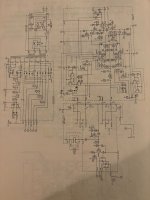
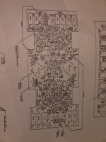
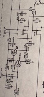
I appreciate all the input! Some pics of a fairly crude DRS250 service manual in case it helps:


Last edited:
The Phase Linear DRS series was introduced in 1982 at a time when Phase Linear was struggling to survive. DRS stands for “Dynamic Range System”.
“Phase Linear was evidently looking ahead to the anticipated growth of digital and other recording systems with large dynamic-range requirements when they designed the DRS series of amplifiers”. (Stereo Review magazine). Former Phase Linear head engineer A.P. Van Meter also told me many years ago that they were working on this technology in order to meet the "FTC required one-third power preconditioning".
The DRS250 is an integrated amplifier version of the DRS400 amplifier. They both share the same “PWR DRIVE” (210-0371) and “PWR SW” (210-0409) pc boards as well as a number of other parts including the same power supply transformer. NOTE: The power supply transformer had a higher than normal failure rate.
The DRS250 and DRS400 “work on a multiple power supply basis. It provides 50 Watts per channel RMS into 8 ohms at the minimum output level. But when your music reaches it loudest passages, The DRS 250 and DRS400 automatically delivers up to 400 Watts of peak power per channel or another 6.02dB of headroom.”
The service manuals for the DRS250 and DRS400 were written at a time when Phase Linear was downsizing and therefore are not as extensive as earlier series 1 and series 2 service manuals were. They include schematics, parts layout, specifications, parts list, and a 1 page “Amplifier Test Procedure”. NOTE: There are no troubleshooting tips.
Step 3 in the service manual states: “Display: monitor the L channel output with an AC voltmeter (no load). Drive the L channel with a 2KHz sine wave. Verify that the DRS indicator lights at 50 Watts RMS (20.0 VRMS) and that the clipping indicator lights at 200 Watts RMS (40 VRMS). Repeat for R. channel.”
Step 9 “Supply switching: Drive both channels with a 2KHz sine wave, increase the level and verify supply switching at the collector (case) of the positive and negative banks. Low supply voltage +/-50VDC, high supply voltage +/-80VDC
NOTE: The MJ1101x series Darlingtons in the DRS series amplifiers had a higher than normal failure rate.
That's useful info. I'm finding better online schematics for the DRS400.
I would also suggest cleaning or replacing the two speaker protection relays, K1 & K2.
They can be big trouble makers on older equipment.
The contacts can wear / corrode and cause a high resistance bad connection to the speakers.
I'm not suggesting it's the only cause of the problems you describe, but it may contribute.
In my experience, this has been a very common problem.
They can be big trouble makers on older equipment.
The contacts can wear / corrode and cause a high resistance bad connection to the speakers.
I'm not suggesting it's the only cause of the problems you describe, but it may contribute.
In my experience, this has been a very common problem.
Thank you for the manual. I do have a B&K scope. Just need to a signal generator and learn to use both. 🤓
@as_audio On Monday you did not own a scope.
Thanks to my brother, by Wednesday I had obtained a B&K scope per post #14.
- Home
- Amplifiers
- Solid State
- Causes of Amp Distorion - Phase Linear DRS250