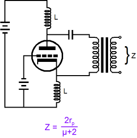
Thansk for proposing this circuit. Broskie is an excellent brain in tube tech.Unless, of course, he uses two identical chokes for loading the plate and cathode and their low DCR can set the bias for the cathode renders no need for an elevated grid as illustrated in the Broskie article. Of course that's a lot of irons (and expensive) for a real world project.
===============
*** off topic ***
Can someone tell me if the gain of the cathodyne like the above example can change if I apply variable negative voltage to the grid to change the bias current if the tube is a remote cut off triode in a compressor circuit? I want to find a way to do compression without resorting to a conventional push-pull circuit.
Schmitz77,
re: Your schematic in post # 20:
The 10uF shorts the input signal to ground
I can not determine all the things you are doing with Rec out, 2.2k, the switch, 1Meg, and 500k pot circuits.
Looks like more detail, or some wiring change will clarify it.
I am guessing the 1 Meg is there to charge-up the 0.1 uF cap, when the switch is at the middle 4 (open positions) of the switch.
The 500k pot wiper might need a large resistance resistor to ground, in case the wiper
ever lifts off the pot (or use a very reliable pot).
The feedback R and C to the driver stage cathode and cathode bias resistor, that comes from Ra 5.1k will slightly affect the balance of the “concertina-like” output stage. But of course the output to the transformer is differential (the difference of the plate and cathode signal voltages). So a slight un-balance condition might not affect anything.
Last edited:
Looks OK apart from 10uF.
I don't think you need the feedback loop around the output stage, but you can try it.
I don't think you need the feedback loop around the output stage, but you can try it.
10uF should block the ground on the isolated Cinch input.
That will not shorten the input signal because its on the cold secondary side of the input trannie.
Same has been done on the famous TAB V76 (I will use external MC input trans).
WE did it a bit different with a 500K resistor to ground and a cap coupled to the cathode.
But all are lifting the input trans signals much above ground to increase pentode input resistance.
Will see if the negative voltage feedback is necessary.
Attachments
Hello,
I noticed Shindo Labs are coupling with a 4uF from the cathode to the symmetrical transformer load instead putting the coupling cap in the anode section as the Broskie circuits do. Will this make a difference resulting in a smaller coupling cap in the cathode because lower output resistance? Or doesn't it matter as this is a symmetrical load?
I could spot they are using the very same topology as shown in this diagram so there is no extra resistor in the cathode for adjusting and determination of the negative input voltage including an extra capacitor parallel to this grid resistor. Its not that I want to copy anything exactly but its interesting that they use an absolute minimalistic approach here.
Attachments
Last edited: