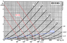
Let's take an ECC83 with two resistors in series on it's cathode.
R1 (directly coupled with the cathode) is 3,3Kohm and in series with it a resistor R2 of 33Kohm, connected to earth. R3 = 1Mohm and runs from gate to the connecting point of R1 and R2.
My question is : why is the voltage on the resistors in series with the cathode getting bigger, while the voltage on the anode gets smaller?
I cannot see this , nor find the theory.
Is the Ri of the tube changing soo much?
Is this a simulation or experiment?
If simulation then maybe you are using a bad model, or using a good model outside its domain of applicability. With a 1M grid resistor you will be affected by any grid current which may be present; valve models often get grid current wrong.
If experiment, then have you built the circuit you think you have built? Are you measuring what you think you are measuring? Is parasitic oscillation an issue?
I am mainly asking about measurements of several of the same katodefollowers in the book of R. zur Linde. He uses this configuration several times.
In his schematics I observered this tendency in dc. adjustment of ECC83 as cathodefollor. I didn't build them all, so I was quite confused. about this behaviour.
So, I only read about it; it was no measurement of mine. But was eager to try.
That's why I asked if this was normal behaviour of the tube.
Siepie, you're making a good argument for owning a variable voltage DC bench supply! If you had one, you could breadboard this in a few minutes, then measure (and plot) the voltages you say you're expecting/reading about.
And you don't even need a variable supply… an anode load resistor which is bypassed with a capacitor! (very odd topology to most, but perfectly reasonable) does the trick also. Can't predict exact voltages, but that's what your digital meter is for. Measure 'em.
GoatGuy
And you don't even need a variable supply… an anode load resistor which is bypassed with a capacitor! (very odd topology to most, but perfectly reasonable) does the trick also. Can't predict exact voltages, but that's what your digital meter is for. Measure 'em.
GoatGuy
Thanks Mona (de raaklijnen zijn inderdaad anders, dus andere dI/dV factoren). I must think this over ; Goatguy,
I'll try it out. DF96, it's a book from 1989, Elektor. Audio &guitar schematics with tubes by R. zur Linde.
I'll try it out. DF96, it's a book from 1989, Elektor. Audio &guitar schematics with tubes by R. zur Linde.
Was that the book in which the author invented new names for everything (or, perhaps, simply transliterated the Dutch names into 'English' instead of using the existing technical English names)? If so, the result was so unreadable that any errors in the text could not be seen.
This was the book that showed circuits with feedback loops around volume controls. It is full of egregious errors and mis-statements. I would suggest using a better book for learning.
One hint which might be relevant: ECC83 will start drawing grid current with Vgk < 1V.
One hint which might be relevant: ECC83 will start drawing grid current with Vgk < 1V.
So it probably was the book I was thinking of. I wondered at the time how a generally decent magaizine could publish such stuff. Proof-reading by someone other than the author would have found most of the problems, but the outcome would probably have been 'reject' rather than 'major revisions'.
- Status
- Not open for further replies.
- Home
- Amplifiers
- Tubes / Valves
- Cathodefollower and strange behaviour with lowering of anode voltage.