Hello, I am new to this tube stuff and I’m reading a book “Design and construction of tube amplifiers” by Robert Megantz.
I understand most of it at this point but there is one item he doesn’t explain well.
In this example he chose a tube, and an operating point and chose a -1.1v grid to cathode voltage. That all makes sense to me.
He then goes on to say that since -1.1v is the desired grid-to-cathode voltage, the cathode voltage should be 1.1v.
He doesn’t explain why the cathode voltage should be 1.1v. Where did he come up with the 1.1v?
I have attached the page, and highlighted the “1.1v” section I am referring to.
Attachments


If look at the curves in the graph, at the operating point, interpolating between the Vg curves, you will find that Vg is approximately -1.1V. A positive cathode voltage means the grid is neqative with respect to the cathode when the grid is at 0V.
That voltage will be determined based on about 6 different reasons, but it starts with the maximum signal that will be applied to the grid. If the peak music signal is 1v, then the cathode needs to be just a little higher to accomodate it. But there are a bunch of design considerations that go into the process. Feedback, tube type, supply voltage...yadda...
One consideration is distortion. To minimize distortion, the Vg curves should be evenly spaced on either side of the operating point along the load line. Second order harmonics are generated when the positive and negative portions of the amplified signal are not equal in amplitude. So, you generally look for regions of the curves where they are most evenly spaced.
Ok I see that, but is there a reason he chose + 1.1v for the cathode?
The grid is at 0VDC relative to ground, and the cathode is at +1.1VDC relative to ground,
due to the cathode resistor chosen.
So the Vgk is then at (0V - 1.1V) = -1.1VDC as desired.
Last edited:

so not really a choice, that -1.1 volt is the grid voltage when a certain cathode current and plate voltage is actually where the tube is at, take note that in real circuit, that will be off by a bit, either higher or lower, so do not be surprised when it does....the tube curves are excellent starting points for any tube design...
Try plotting the line Vgk = Rk x Ip on the curves, with one point for each different Vgk shown on the graph.
You can do that for several different values of Rk.
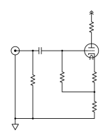
It is possible to decouple the value of Rk and the value of Vgk with a circuit like this. Now Vgk can be less than Vk-ground. Also, the grid resistor is bootstrapped to a higher impedance level, so a smaller capacitor can be used.
You can do that for several different values of Rk.
It is possible to decouple the value of Rk and the value of Vgk with a circuit like this. Now Vgk can be less than Vk-ground. Also, the grid resistor is bootstrapped to a higher impedance level, so a smaller capacitor can be used.
Attachments
Last edited:
I understand your question to be "Why not some (any) other choice?. What decisions are made to choose this one?" Not having seen the book, I can't say whether or how this question is covered, but I'd make a good guess that it's not covered much - it never is, because it's one of those issues that's best taught in person. A whole chapter of a book could discuss optimum loadlines and optimum idling (zero signal) choices, and still leave a lot of room for discussion.is there a reason he chose + 1.1v for the cathode?
The general order of decisions is to first determine how much output voltage swing and into what load the stage will operate. (If the required output is very small, then amplifier noise is instead the first bit.) Then one sits down with the valve's characteristic curves, cuts and tries various options, looking for best linearity, iterating until happy. Linearity is pretty easily observed with a practiced eye, but takes a lot of words to describe. As a baptism in holy water, I'd recommend RDH4, which is available as a download. Even better is finding somebody local to coach, but that's tougher these days than it once was.
If I'm off base in reading your question, come back with the question framed differently, and we'll all pitch in.
All good fortune,
Chris
Because it's roughly in the middle of the loadline and the calculation ends up giving you a nice round number: 1000 ohms.
http://valvewizard.co.uk/Common_Gain_Stage.pdf
http://valvewizard.co.uk/Common_Gain_Stage.pdf
Last edited:
And at this point, the arguments will begin. Is the bias choice for maximum output better or not than one for lowest distortion at (a smaller) required output? How much margin is required? How close to zero bias can I get with x source impedance and a bogey valve without having to worry about that as a distortion source? How high the moon?
As much as I admire your excellent books and generously provided website, First Class and highly recommended, also Bob Cordell's book and RDH4 (and 3, more about inductors!), and the wealth of information here on diyAudio and everywhere online, I still encourage folk to seek out a coach/teacher for some things. It's very hard to learn math without a teacher, and some electronics topics fall into a similar blind spot, looking fairly linear and predictable on the surface, but suddenly bottomless, like a scary ocean front. This viewpoint comes from my personal experience, so may well be different for other folk. Learning is always personal.
Much thanks, as always,
Chris
the RCA tube databooks have tables already prepared for rc coupled triode pentode voltage gain stages, you have a choice of maximum gains or maximum output swings and anything in between...
- Home
- Amplifiers
- Tubes / Valves
- Cathode voltage