In my research on various PS layouts, I was curious of a couple. The use of a cathode follower in driving the pass tube, and my question is why this wasn’t used more often?, if one is looking for greater frequency response, and lower output impedance, this is one way of accomplishing that. I have found only two schemes that implement this topology, and I have developed my own.
Attachments


Cathode followers to drive series pass tube usually are unncessary and complicates the design. Unnecessary because series pass needs to operate within linear regime with grid negative respect to cathode and thus no grid current is drawn. Also complicates the design because you need to waste cathode follower current out of series pass grid, with extra effort and extra energy loss.
In any case, the US2519377 patent will solve some questions.
In any case, the US2519377 patent will solve some questions.

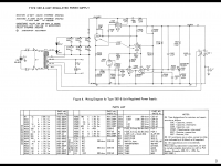
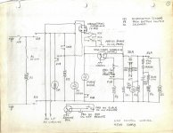
It all depends on the needed ouput power.In the first schematic there are 6 paralleled 6l6 tubes.When the output current is high, the input to output voltage gets low and the tube starts to draw grid current so you need a follower to drive the tubes and prevent output current collapse.That's also distructive for the power tubes in the long run...
Some good points, on a side note, the Navy Manual states that there are very few maintenance records on the first drawing, Im assuming it’s a very reliable design.It all depends on the needed ouput power.In the first schematic there are 6 paralleled 6l6 tubes.When the output current is high, the input to output voltage gets low and the tube starts to draw grid current so you need a follower to drive the tubes and prevent output current collapse.That's also distructive for the power tubes in the long run...
Early on in my career (1959?) I did one, a 12B4 driving 3x6N7s.
And then another, this one brute force, 4.5 KV at One Ampere.
The passers where three of 304TH, the CF I recall was an 813.
That would be circa 1962.
And then another, this one brute force, 4.5 KV at One Ampere.
The passers where three of 304TH, the CF I recall was an 813.
That would be circa 1962.
Attachments
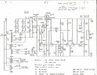
This is a very interesting design, I noticed you used a voltage divider to lower the reference and it feeds both comparators.Early on in my career (1959?) I did one, a 12B4 driving 3x6N7s.
And then another, this one brute force, 4.5 KV at One Ampere.
The passers where three of 304TH, the CF I recall was an 813.
That would be circa 1962.
The use of a cathode follower in driving the pass tube, and my question is why this wasn’t used more often?
I have not seen many audio power amps having tube regulated supplies. In preamps wide bandwidth regulation trumps low output impedance and high current delivery. The inclusion of a follower adds a pole and makes nfb harder to stabilise.
Of course not, although I have seen Audio Research use regulated screen supplies on the output tubes, and By wide bandwidth Your implying good audio frequency response? From what I know about the first regulator I posted, it would give excellent results if you need just +150VDC, wouldnt it?I have not seen many audio power amps having tube regulated supplies. In preamps wide bandwidth regulation trumps low output impedance and high current delivery. The inclusion of a follower adds a pole and makes nfb harder to stabilise.
For MAXimum gain for maximum PSRR, we often used >1Meg load on the voltage amplifier. But data for power tubes specified <0.5Meg for grid path resistance. Conflict!!
There are reasons why you can cheat this away. The max grid resistance is not for Cathode Follower duty, where Rg may plausibly be Mu(g2) higher. OTOH the pass tubes lead a tough life, can get gassy. And SIX low-bid high-hours 6L6 can add-up to major gas current. Also a mil-spec design goes through many layers of Approvals and many of these men are passed-over designers (promoted to the approval desk to keep them out of the design office).
There are reasons why you can cheat this away. The max grid resistance is not for Cathode Follower duty, where Rg may plausibly be Mu(g2) higher. OTOH the pass tubes lead a tough life, can get gassy. And SIX low-bid high-hours 6L6 can add-up to major gas current. Also a mil-spec design goes through many layers of Approvals and many of these men are passed-over designers (promoted to the approval desk to keep them out of the design office).
I was looking over your schematic, and couldn’t recognize the Pentode-Triode, I drew this in B2 Spice using a 6BL8 and it does very well! Nice job.Early on in my career (1959?) I did one, a 12B4 driving 3x6N7s.
And then another, this one brute force, 4.5 KV at One Ampere.
The passers where three of 304TH, the CF I recall was an 813.
That would be circa 1962.
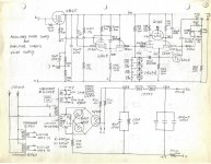
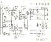
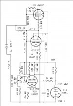
Here is another regulated PS with the 3x 6N7 passer & 12B4 CF, This one uses a simpler error amp.
I did several small regulated PS around that time for minor apps around the lab.
Tried various passer tubes such as 807, 6550, 6L6, 6B4 & so on. And 6AS7G/6080.
During that period the research was on magnetic core memory.
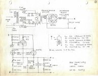
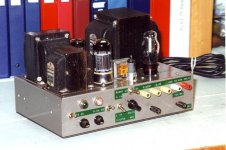
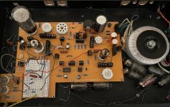
Still using something similar as my own, home grown version. Its on a Hammond 8x12x3 Steel Chassis.
Can switch between C or L input to filter. The 5AR4 can be pulled & replaced by SS subs by myself or New Sensor.
The sub rectifier I put together uses 2KV diodes from Philips. There is also a jumper plug that can be stuffed into the 6080
slot so that the full out put of the bare PS is available. And a negative 150V for biasing. And 6,3V, 4A for heaters
All but the negative is on the front binding posts. Everything available on an octal socket on the backside.
I did several small regulated PS around that time for minor apps around the lab.
Tried various passer tubes such as 807, 6550, 6L6, 6B4 & so on. And 6AS7G/6080.
During that period the research was on magnetic core memory.
Still using something similar as my own, home grown version. Its on a Hammond 8x12x3 Steel Chassis.
Can switch between C or L input to filter. The 5AR4 can be pulled & replaced by SS subs by myself or New Sensor.
The sub rectifier I put together uses 2KV diodes from Philips. There is also a jumper plug that can be stuffed into the 6080
slot so that the full out put of the bare PS is available. And a negative 150V for biasing. And 6,3V, 4A for heaters
All but the negative is on the front binding posts. Everything available on an octal socket on the backside.
Attachments
I think a cathode follower can be useful to drive a pass tube when low voltage drops are mandatory, as with positive grid voltages the typical concave triode plate curves become convex, resembling tetrode or pentode curves. Anyway, the tube needs to cope with this kind of operation.
Best regards!
Best regards!
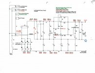
I like this arrangement alot, Ive used it for several +300VDC regulators, a triode-pentode may be a better substitute for the cathode-coupled pair possibly driving a cathode follower, and a pair of 6AU6 pentodes may do a better job than the 12AX7's for the main error amplifier.
Attachments
One difference between what the author shows and my examples is that there is a series resistor tied to the cathode of the follower and the grid of the pass tube to ground, this would limit the amount of grid current the pass tube would draw.Cathode followers to drive series pass tube usually are unncessary and complicates the design. Unnecessary because series pass needs to operate within linear regime with grid negative respect to cathode and thus no grid current is drawn. Also complicates the design because you need to waste cathode follower current out of series pass grid, with extra effort and extra energy loss.
In any case, the US2519377 patent will solve some questions.
OK, but as limit the grid current, your pass element may be limited in anode current too, reducing the output voltage and running out of regulation when anode cathode voltage is low and load current is high.
This exactly is one of the situations I've meant in #13 😉 . Low plate to cathode voltage drop is mandatory here. Positive grid voltage and a suitable tube, either a triode or a triode strapped tetrode/pentode, may save a regular pentode's additional screen supply.
Best regards!
Best regards!
Under heavy load the grid of the passer needs to be pulled up close to the cathode.
So for example a 6AU6 or whatever is used, its plate resistor needs to go to a much more +ve place.
In common designs that is often the raw DC out of the Rectifier/Filter combo.
Some designs pull that up even further.
Some volk try running the subject plate to the regulated +ve lead. Sometimes in such designs
the regulator locks up & refuses to start.😱
It would be interesting to take a reading to some old papers. I found myriads of data from old papers freely available on the net. The most juicy IMO is one from Hunt and Hickman "On Electronic Voltage Stabilizers" from 1939. Its the oldest I could find and many future literature makes reference and take concepts from it. I suggest to take a reading: it is very deep and explanatory.
Another one is "Basic Theory and design of Electronically Regulated Power Supplies" by A. Abate Proceedings IRE July 1945.
Still more on "Stabilized Power Supplies" M. G. Scroggie, Wireless World october 1948.
One more is "Design of Electronically Regulated Power Supplies" by Ben Penners and W. Davis Radio, feb. 1947.
Last edited:
- Home
- Amplifiers
- Tubes / Valves
- Cathode Followers and Pass Tubes