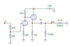
fscarpa58 said:2W for 20k e 30k res
for the other ( 200, 1meg, 270k) also 0.2 W.
I like the topology very much but, in this case,
and with 6N1P, we need 300 V to have it working properly.
Owing to the constrain due to the rigid connection
between plate of 1th tube and grid of the 2nd, the working
point is not very good, that is high distortion
( 0.4% at 5Vrms out) and not very great max swing.
However it works and maybe you will like its
sound.
If you don't need gain the CF is advisable.
Federico
Thanks Federico! Will give you updates soon.
Federico,
I agree with your comment about the poor operating point of the direct coupled CF. It does not sound so good.
However, the configuration has a huge advantage.
If the output is taken from the plate of the first tube, not from the cathode of the second, and if the plate resistor is made equal to the cathode resistor, then we have perfect current balance as long as the plate is held at half B+.
This means that the current draw of the two triodes will add to a constant; viz, perfect current balance. This makes power supply design very easy, and improves the bass performance a great deal because there is no voltage sag on the B+.
In 1999, John Broskie of Tubecad.com came up with this approach; I think it is very clever.
Cheers,
Hugh
fscarpa58 said:However
this has about 25 db of gain.
I really do not like it.
federico, are those (in post #16) values for ecc88, or some other tube? if its not, could you recalculate for me....
i'll be grateful
Hi trancy
You have to decide.
post #16 is addressed to JojoD.
The cir has high gain, 150 V B+ supply,
it is tuned for 20k load, and uses 6n1p.
I post a message for you a few days ago.
It was a 3db gain with 100V B+, uses 6DJ8/Ecc88
and was tuned for 4.7k load.
let me know.
Federico
You have to decide.
post #16 is addressed to JojoD.
The cir has high gain, 150 V B+ supply,
it is tuned for 20k load, and uses 6n1p.
I post a message for you a few days ago.
It was a 3db gain with 100V B+, uses 6DJ8/Ecc88
and was tuned for 4.7k load.
let me know.
Federico
In 1999, John Broskie of Tubecad.com came up with this approach; I think it is very clever.
Hi Hugh
I agree with you, and I also consider
Broskie idea a very good one.
Federico
fscarpa58 said:Hi trancy
You have to decide.
post #16 is addressed to JojoD.
The cir has high gain, 150 V B+ supply,
it is tuned for 20k load, and uses 6n1p.
I post a message for you a few days ago.
It was a 3db gain with 100V B+, uses 6DJ8/Ecc88
and was tuned for 4.7k load.
let me know.
Federico
sorry for inconvenience federico,
I"ll try to make CF on 100V B+ with ECC88 from your schematic, and also I want to try on 150V B+ with same sch.(if I"m correct, higher B+ is better for sound quality)...
........
is there any simple formula to recalculate values, or its nessesary to have some tube related sw?
I really dont want to bother you federico, but...you know....I dont know anything about tubes...this is my first one....practicly I am a tube virgin....ohhhhh yeaaahhh....
Trancy
I am happy to help you.
But I need clear data to work on.
1) type of circuit
2) tube
3) gain
4) B+
5) load
If you only want that I recalculate values for circuit of
post #8, here is the pic.
Federico
I really dont want to bother you federico
I am happy to help you.
But I need clear data to work on.
1) type of circuit
2) tube
3) gain
4) B+
5) load
If you only want that I recalculate values for circuit of
post #8, here is the pic.
Federico
Attachments
great...thanks federico.....
thats all I want this moment....i will report you, how its work....
thats all I want this moment....i will report you, how its work....
federico,
those values of resistors, is enough for 14K resistor to be 1/4W, and for 200E 1W ?
Is it O.K., if I use 14,7K instead 14 and for 180 ohms instead 200 ohm....?
its hard to find exact values ( I have 14,7K and 180 E)...
thanks
ciao
those values of resistors, is enough for 14K resistor to be 1/4W, and for 200E 1W ?
Is it O.K., if I use 14,7K instead 14 and for 180 ohms instead 200 ohm....?
its hard to find exact values ( I have 14,7K and 180 E)...
thanks
ciao
Is it O.K., if I use 14,7K instead 14 and for 180 ohms instead 200 ohm....?
Yes , it's o.k.
is enough for 14K resistor to be 1/4W, and for 200E 1W
No, actual static dissipation of the 14.7k res. is a bit less
of 0.5 W so I advice you to use at least 2W to 4W res.
the 200R res dissipates less of 10 mW so you can safely
use 0.1W res
Federico
hello again....
mu cf by the schematic in post 27 working fine.
what it will happened, if I drop B+ voltage to 90V....or what should I change??
Its a little bit of hum (buzz) present...could be a bad rectified supply cause of that?
mu cf by the schematic in post 27 working fine.
what it will happened, if I drop B+ voltage to 90V....or what should I change??
Its a little bit of hum (buzz) present...could be a bad rectified supply cause of that?
Nope, bad rectifier wouldn't hae any DC at all. Check grounds, filtering and heaters. Especially if the heaters are floating.
Tim
Tim
hi
try disconnecting the heater while the
cir is on. usually it takes a few seconds
to go off due to thermal inertia.
See if during that time something changes.
Then, with cir on, try to move your fingers
near various part of the cir and see when
the hum increase further. Also touch
the cir. if you find some critical point
try to change layout there or use shielded
cable there. change ground path.
Try with cir in and outside the box if
you use one.
Federico
what it will happened, if I drop B+ voltage to 90V
It will work but with a greater distortion.
Not so bad however.
Federico
fscarpa58 said:hi
try disconnecting the heater while the
cir is on. usually it takes a few seconds
to go off due to thermal inertia.
See if during that time something changes.
Then, with cir on, try to move your fingers
near various part of the cir and see when
the hum increase further. Also touch
the cir. if you find some critical point
try to change layout there or use shielded
cable there. change ground path.
Try with cir in and outside the box if
you use one.
Federico
cir???? something new for me
I connect ground of heater (minus) on ground (is that o.k.?), and hum was half lower , after that i noticed, that when I touch speaker connector with osciloscope ground, its almost o.k. ????? power stage is dead quiet, when I disconect mu cf. Today I will try to change position of ground point, or maybe there is some other suggestions?
fscarpa58 said:
Excuse me
cir stands for circuit
federico
of course...
i fell stupid....here is so many contraction....they make me confuse
fscarpa58 said:Trancy
I am happy to help you.
But I need clear data to work on.
1) type of circuit
2) tube
3) gain
4) B+
5) load
Federico
hello
could you please....you know what.....help me....with recalculation....
1. circuit is attached
2. tube is ecc88 by siemens
3. more than 3
4. 100V
5. 4k7
correct me if I'm wrong: gain of tube is defined by u (for ecc88=33) and plate resistor (Rp)
thanx
Attachments
- Status
- Not open for further replies.
- Home
- Amplifiers
- Tubes / Valves
- cathode follower with gain