Cathode follower - resistor calculations
Does anyone know of some suitable software which assists in calculating cathode resistor values for the Broskie Cathode follower circuit?
I am currently using the Broskie Cathode Follower circuit with 12AT7 tubes, and need to calculate the correct values for Rk based on B+ = 300.
Attached is the chart which Broskie includes in his manual, however I have no idea how he determines Rp for a given B+.
He gives the formula for calculation as:
Iq = B+/2(rp + [mu + 1]Rk)
So, for the 12AT7, how do we know what the optimal Iq is when the B+ is in fact determining Rp?
Attachments

Last edited:
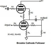
Circuit here for reference.
Note I am using R1 = R2 = R4 = R5 as 100k (not relevant for the formula above).
Currently in the circuit I have B+ = 300
Rk = 300R
From the datasheet, I can see that a PLATE VOLTAGE of 250 gives an Rp of 15000 - so we have (roughly)
Iq = B+/2(rp + [mu + 1]Rk)
Iq = 300/2(15000 + (60 + 1)300)
Iq = 300/66600
= approx 4.5mA
My concerns are; (a) but that's all based on an incorrect Rp, how do we determine the exact Rp for a given B+, and (b) how do we know if this 4.5mA (when finally correct) figure is optimal for the tube?
Attachments
Last edited:
Others will have to chime in on this but here's from me.
Rp is not constant like you said. It depends on the B+.
mu is relatively constant and it's the product of Rp * gm.
Your best bet is to find this transfer characteristics from the datasheet.
If you have that, then the steps are:
1. Determine the Iq that you want. Keep the power dissipation within limits. You want as much Iq as possible while keeping to tube life long enough.
2. Check on the transfer characteristics above and see where rp falls.
3. Determine Rk using Broskie's formula.
Just remember, each valve gets half of B+. Knowing this and any Iq of your choosing, you can also draw a load line and determine Rk from there.
Again, let others chime in. I also would like to know more about this, especially if i'm making wrong assumptions.
Rp is not constant like you said. It depends on the B+.
mu is relatively constant and it's the product of Rp * gm.
Your best bet is to find this transfer characteristics from the datasheet.
An externally hosted image should be here but it was not working when we last tested it.
If you have that, then the steps are:
1. Determine the Iq that you want. Keep the power dissipation within limits. You want as much Iq as possible while keeping to tube life long enough.
2. Check on the transfer characteristics above and see where rp falls.
3. Determine Rk using Broskie's formula.
Just remember, each valve gets half of B+. Knowing this and any Iq of your choosing, you can also draw a load line and determine Rk from there.
Again, let others chime in. I also would like to know more about this, especially if i'm making wrong assumptions.

You can use the conversion factor 300/250=1.2 to estimate the rp'. so assuming the same Ik, then rp' = rp / 1.2 = 15000 /1.2 = 12500. Since the CF has 100% feedback, its linearity is very good, so any current will do a good job (within reason of course).
Checking from 12AT7 datasheet i found, max dissipated power is 2.5 watts.
So for a plate voltage of B+/2 = 300/2 = 150 volts, that corresponds to 2.5/150 = 16.67mA of maximum plate current. Aiming for about half of that, here's the quiescent point.
So, with Iq = 7.5mA, Rk should be around 133 ohm.
Let's try to see if we get the same result using Broskie's formula and rp value from jazbo8
Iq = B+/2(rp + [mu + 1]Rk)
7.5mA = 300/2(12500 + (60+1)Rk)
mu is 60 from the spec sheet and i end up with
Rk = 123 ohm. Soo.. not so different than the first method. I think you should be ok with 120 ohm.
Again, others should confirm this as i'm not so sure myself.
So for a plate voltage of B+/2 = 300/2 = 150 volts, that corresponds to 2.5/150 = 16.67mA of maximum plate current. Aiming for about half of that, here's the quiescent point.
An externally hosted image should be here but it was not working when we last tested it.
So, with Iq = 7.5mA, Rk should be around 133 ohm.
Let's try to see if we get the same result using Broskie's formula and rp value from jazbo8
Iq = B+/2(rp + [mu + 1]Rk)
7.5mA = 300/2(12500 + (60+1)Rk)
mu is 60 from the spec sheet and i end up with
Rk = 123 ohm. Soo.. not so different than the first method. I think you should be ok with 120 ohm.
Again, others should confirm this as i'm not so sure myself.
The Broskie CF is basically an SRPP with 100% NFB. This means the plate to cathode voltage of each tube is close to B+/2 so working out Rk is simply a matter of choosing an operating current and using the plate curves to find the corresponding Vgk. The big question is what current to choose. Many people would say pick as large a current as possible to get the tube into a more 'linear' region. The problem with that is than an SRPP creates its lowest distortion into a given load at a specific operating current and hence specific value of Rk. This is fine where you know the load and it is definitely fixed but often neither is the case. Whatever the operating point, the mu of 60 and 100% NFB is going to reduce distortion at normal hi-fi operating levels to very low values. There is therefore no point is operating the tube close to maximum dissipation so I would recommend setting an Ia of 4 to 5mA.
Cheers
Ian
Cheers
Ian
Ok thanks for all the feedback, a good discussion.
These are exact measurements of the current setup (stock build):
B+: 313v (dc)
Plate voltage Triode 1: 153.8v
Plate voltage Triode 2: 124.6v
Rp: 300R
Mu: 60
Thus;
313/2(12500 + (60+1)300)
= 5.08mA
So, given we seem to accept that linearity and low distortion are typical of this circuit regardless of the plate current (within reason), it appears that the current Rk of 300R is ok.
The only questionable figure is the Rp of 12500, which could be inaccurate.
Are there any other measurements that could be taken to assist in optimising the system? Presumably the 12AT7 is one of the better choices in this circuit due to its high transconductance.
FWIW, I can see that the grid-cathode voltages are as follows:
Triode 1: 1.22v
Triode 2: 0.98v
Last edited:
Isn't the B+ tied to the top triode? If so, how can you have different voltages? Also 313V exceeds the rating for the 12AT7.
Sorry that's only measuring a single valve (each one is a double triode).
So what I'm measuring is the voltage between:
Pins 1 and 3: 153.8v
Pins 6 and 8: 124.6v
Even on the PCB when I measure from the B+ to GND terminal it is 313v, but if I measire GND to PIN 1 of the tube, it shows 155v...so somewhere along the line the B+ is being split by the two valves (as BallPencil points out above).
Have you checked the maximum heater to cathode voltage rating for your 12AT7. The cathode of the top triode will be at a high voltage with respect to the cathode of the lower triode. I assume that your heater supply will be tied to about +150V or you might have problems.
Have you checked the maximum heater to cathode voltage rating for your 12AT7. The cathode of the top triode will be at a high voltage with respect to the cathode of the lower triode. I assume that your heater supply will be tied to about +150V or you might have problems.
I notice the datasheet says peak -ve and peak +ve heater to cathode rating is 90v. What pins do I need to measure to check what it is running at?
I notice the datasheet says peak -ve and peak +ve heater to cathode rating is 90v. What pins do I need to measure to check what it is running at?
Well, looking at the Wikipedia article on the 12AT7, the heater pins are labled 4, 9 and 5. The cathode pins are 3 and 8. So, when your circuit is operating, the lower triode cathode will be a few volts above ground (determined by plate current and Rk) and the upper triode cathode voltage will be about 150V + a few volts. The heater circuit should be within 90V of both voltages (because of heater to cathode voltage rating). So the heater supply (6.3 V or 12.6V as you choose) must be tied at a dc potential of about 80V (not the 150V of my earlier post). You could take the common pin 9 of the heater circuit and connect it to a two resistor voltage divider across the 300V supply and calculated to give (something like) 80 V . Add a decoupling capacitor to ground keep things quiet. Remember that the heater pins 4 and 5 will be 6.3 V +ve or -ve with respect to pin 9; this should be included in your calculations to get the worst case heater to cathode voltages.
Oh, I forgot to add that if your heater supply feeds other tubes then you should check that the other tubes' heater/cathode voltage ratings will not be exceeded.
Oh, I forgot to add that if your heater supply feeds other tubes then you should check that the other tubes' heater/cathode voltage ratings will not be exceeded.
Thanks - good point.
The heater supply also feeds the input tubes (gain stage) which are 6CG7 tubes. The heater/cathode voltage for these is different again.
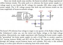
I consulted Broskie's manual (see attachment) and it would appear the best option is to float the heater supply as he mentions in the final paragraph.
Are there any drawbacks to this approach?
Attachments
Yes.. you should float the heater supply to about 1/4th of B+
No drawbacks that i know of.
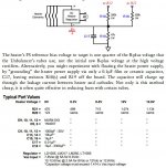
Here's the power supply design for my Aikido preamplifier.
Might give you some ideas.

WARNING. The voltage divider should be in kiloohm not ohm! So, it's 300k and 100k.
No drawbacks that i know of.
Here's the power supply design for my Aikido preamplifier.
Might give you some ideas.
WARNING. The voltage divider should be in kiloohm not ohm! So, it's 300k and 100k.
OK - Broskie appears to suggest either making the PS reference bias 1/4th of the B+ that the tubes use through the installing of R18 and R18 and C17 (0.01uF).
That's the way I have it set up now (the PCB has the PSU and the linestage circuit all included) But I have no idea how to measure what the bias reference voltage is. Given the B+ is 315v and I have R18 as 300k, and R19 as 47k presumably it is roughly 315/4 = 78v?
This is probably too high, need to increase R19 to 100k I think.
As you can see by the attachments, he has two different versions of this circuit from differing manuals.....
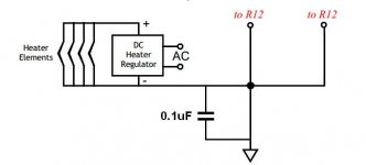
But (and what interests me given the simplicity) he also states you can increase C17 to 0.1uF and remove R18 and R19 altogether to float the heaters - but won't that mean that there is no reference voltage?
That's the way I have it set up now (the PCB has the PSU and the linestage circuit all included) But I have no idea how to measure what the bias reference voltage is. Given the B+ is 315v and I have R18 as 300k, and R19 as 47k presumably it is roughly 315/4 = 78v?
This is probably too high, need to increase R19 to 100k I think.
As you can see by the attachments, he has two different versions of this circuit from differing manuals.....
But (and what interests me given the simplicity) he also states you can increase C17 to 0.1uF and remove R18 and R19 altogether to float the heaters - but won't that mean that there is no reference voltage?
Attachments
Last edited:
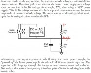
It is the voltage across the 47k resistor.But I have no idea how to measure what the bias reference voltage is.
Given the B+ is 315v and I have R18 as 300k, and R19 as 47k presumably it is roughly 315/4 = 78v? This is probably too high, need to increase R19 to 100k I think.
If you do that then the heater bias voltage will increase. The heater-cathode voltage will therefore also increase as far as the lower valve is concerned, but it will decrease as far as the upper valve is concerned. The only fair way is to bias to 1/4 of the supply voltage so that both valves see the same heater-cathode voltage (at least at idle).
The heaters will then float to a voltage determined by the heater-cathode leakage currents, which could be anything. Floating the heaters is a bit dodgy. In an ideal world you would have a separate heater supply for each of the two valves.to float the heaters - but won't that mean that there is no reference voltage?
- Status
- Not open for further replies.
- Home
- Amplifiers
- Tubes / Valves
- Cathode follower - resistor calculations/software