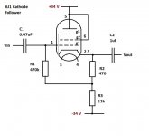
Please can you check my circuit diagram. It is cathode follower (approx. unity gain) using 6J1 valve.
I am not 100% sure of the following:😕
1. Connection of g2 - pin 6 to pin 5 ok?
2. Do I need to make one connection to either pin 2 or 7 or connect both together?
3. Values of C1 and C2. The circuit is intended to have cut off at 25 kHz.
PS don't worry about heater wiring - I have that part figured out 🙂
Attachments
Looks good.
A few suggestions :
R1 can be reduced to , lets say 100k to reduce the risk of grid current. It won't affect input impedance as it's a "bootstrapped" circuit.
A "lead-out" resistor of 100 ohm should be used between cathode and cap to prevent
any tendencies of oscillating. For the same reason, a grid-stopper of 1k should be connected between the grid and the input. Both the lead-out and gridstopper should be
mounted directly in the tubesocket.
You might add 470k both to the input and output caps to ground, this is to prevent
"thumps" when connecting/disconnecting
It's OK1. Connection of g2 - pin 6 to pin 5 ok?
Connect them together.2. Do I need to make one connection to either pin 2 or 7 or connect both together?
Those capacitors determine the LOW cutoff frequency. The HIGH cutoff frequency will be far beyond 25kHz.3. Values of C1 and C2. The circuit is intended to have cut off at 25 kHz.
- Status
- Not open for further replies.
