Hi
I built a self-biased 12AX7 cathode follower with the usual sort of values:
Rk bias resistor 1k5
RL cathode load resistor 56k
Rg grid-leak 470k tied to junction of Rk and RL
When I power it up from a 300V supply, there is about 70V at the tube cathode, about a volt and a half across Rk but the grid is at about 45V. I have built this using different sockets, different tubes, and different resistors and the voltages always come up weird.
If I short RL then the grid is at zero volts, cathode at 1V5. The current through the tube seems the same either way.
I thought maybe there was something going on during the warm-up and added a grid protection diode. This did not change anything.
With the voltages present I would expect the tube to be off, but it works and passes signals like it should. The DSO 100MHz scope shows no oscillations or noise.
How can this be? Does anyone have any ideas?
Thanks
1 Mohm meter input resistance?
What voltage do you measure across the 470 kohm grid leak resistor, so with one meter terminal connected to one side and the other to the other side of the resistor?
What voltage do you measure across the 470 kohm grid leak resistor, so with one meter terminal connected to one side and the other to the other side of the resistor?
If you are measuring using a typical DVM its input resistance (considerably < 1M based on your measurement) is loading down the grid connection when you measure to GND.
Always post a complete schematic with the questions. Unless you have a 10M or higher input impedance voltmeter,I built a self-biased 12AX7 cathode follower with the usual sort of values:
don't try to measure high impedance nodes, since it will be too inaccurate. Like this one.
https://www.ebay.com/itm/325355826561?
An indirect test could be shorting across the 470k resistor. If the other voltages remain the same,
you can rule out a leaking coupling capacitor.
Last edited:

I made a mistake, a meter resistance far greater than 1 Mohm, about 20 Mohm in fact, can cause the problem because the cathode follows the grid.
The input resistance is about 13 Mohm, if I calculated it correctly. That's Rg (1 + RL/(Rk + 1/gm)) + RL. A resistance of 23 Mohm to ground then reduces the voltage from 70 V to 45 V.
The calculation may be a bit too pessimistic because I neglected the effect of the valve's internal resistance. That should make it a bit better, but not much. All in all, I estimate that your meter has an input resistance of about 20 Mohm and that that causes the issue.
Last edited:
Your measurements are correct if your meter has DC resistance of 20 Mohm.I built a self-biased 12AX7 cathode follower with the usual sort of values:
Rk bias resistor 1k5
RL cathode load resistor 56k
Rg grid-leak 470k tied to junction of Rk and RL
When I power it up from a 300V supply, there is about 70V at the tube cathode, about a volt and a half across Rk but the grid is at about 45V....
See the simulation w/ and w/o meter connected to grid ...
Attachments
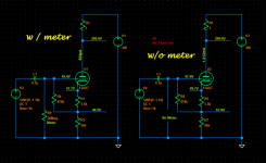
Aside from Sorento's brilliant diagram: it is good to have two meters. Monitor the cathode with a semi-cheap meter while you poke the grid with the good meter. The cathode voltage drops!! A clue that you are upsetting the circuit in a way that may not happen in normal life.
It is not really possible to read the dc voltage at the grid of a cathode follower. The loading of the meter alters the bias point and gives a strange reading. Just assume the grid voltage is the same as that measured at the other end of the grid leak resistor.
Cheers
ian
Cheers
ian
It's essentially bootstrapping, bootstrapping increases the input resistance from 470 kohm to just over 10 Mohm. What you can measure is this:
The voltage to ground at the node where Rk, RL and Rg are connected to each other
The voltage across the grid resistor (one meter terminal connected to one side and the other to the other side of the resistor, so the meter is in parallel with the resistor)
You can then calculate the grid voltage.
The voltage to ground at the node where Rk, RL and Rg are connected to each other
The voltage across the grid resistor (one meter terminal connected to one side and the other to the other side of the resistor, so the meter is in parallel with the resistor)
You can then calculate the grid voltage.
WOW !!
Thank you so much everybody !!
I did a simulation and it had all the expected voltages on it but I did not think to add the meter resistance. It makes perfect sense that the meter would upset the CF.
Most scopes and DVMs are 10M or higher, as far as I know.
Anyway - mystery solved 😍
Thank you so much everybody !!
I did a simulation and it had all the expected voltages on it but I did not think to add the meter resistance. It makes perfect sense that the meter would upset the CF.
Most scopes and DVMs are 10M or higher, as far as I know.
Anyway - mystery solved 😍
Hi
Despite my 70 yrs around valves in radio,tv and audio, I recently was also puzzled by observing the odd voltage behavior when measuring cathode follower grid volts - I had to smile when it dawned on me that I had overlooked the cardinal rule of measuring bias volts - bias is between grid and cathode!
Eureka!
Most scopes and DVMs are 10M or higher, as far as I know.
Scopes have 1M input impedance for x1 probes, or 10M for x10 probes, or 100M for x100 probes.
Extending Rayma's list:Most scopes and DVMs are 10M or higher
The classic 'scope is 1Meg; 10Meg with a X10 ......
The classic (US?) VTVM is 11Meg (10Meg internal plus 1Meg in the DC probe).
One series aimed for 22Meg. HP had some much higher.
DMMs seem to round to 10Meg, though I have seen 3Meg and 2Meg and 400k.
Non-experienced "open source projects" designers can do odd things.
- Home
- Amplifiers
- Tubes / Valves
- Cathode follower has strange voltages but works