There is an old hybrid circuit made for Klarskov Mortensen in TAA Magazine I think year 89 with Lateral mosfet(2SK134/2SJ49) double in parallel out but this is drove by a ECC82 in White Follower that has lower impedance.
Maybe is better for you cause you have more 5983 but is easy to find ECC88 at all.
Maybe is better for you cause you have more 5983 but is easy to find ECC88 at all.
I mean simply the output impedance before feedback is considered, i.e. ra||Rk, or roughly 10k||12k in this case.Sorry Merlin, I don't understand your sums. What do you mean by "an open-loop output impedance of 5.5k"?
That's true until you add the grid leak resistor. When you do that, you are feeding back a portion of the output voltage to the grid in phase (positive feedback). However, you right that I got my sums wrong! In this case roughly x0.009 of the output signal is fed back, so the total negative feedback fraction is 1-0.009 = 0.991. Oops! The feedback factor is therefore 1+0.991x5 = 5.995, so the output impedance should be roughly 5.5k/5.995 = 0.92k, plus the OP's bias resistor, or 2.92k. Not great for driving a 3k load.A CF always has a feedback factor of 1.
Infact, the OP's circuit seems to have an input resistance of more like 3k||10k||10k. Yikes!
Last edited:
But Monsieur Billy change the circuit, now is using direct coupling and he put away the bias resistor in series with the load. Thanks again for share de math disquisition now is more didactic for beginners like me.
why should I get 500 Ohms and practically do I get as much as 10 K !
is it kind of instanteneous value only valid for small swings of signal ?
The cathode follower output impedance is ~1/gm.
Cathode Follower Output Impedance Calculator
Thanks Merlin and Dady.
I also got to this conclusion by looking at the internal resistance (ro) of each valve. I believe the Zout cannot be lower than this ro and the circuit will add to it according to its possibilities.
The ECC88 has a ro about 2,3 k hence the total Zout would be in this region, better than the current rough 7 K I get. I figure out that the Zout is the value of the load resistor which gives a signal attenuation of 50%.
The IRFP solution has an internal resistance which is tiny, it would give out a better soution but with solid state help.
Well, I understood now why this high Z happens, many thanks to all of you.
I will try a power triode system, I have wonderful 6080 (6AS7) used as power triodes with enormous success elsewhere. They are just fabulous on music. They should play the trick. I can remember its ro is about 200 Ohms.
The grid leak resistor in an AC-coupled CF is usually sufficiently high in value that it doesn't greatly reduce the input impedance or raise the output impedance. However, if fed from a high impedance source then it can be significant, and can sometimes catch people out.Merlinb said:That's true until you add the grid leak resistor. When you do that, you are feeding back a portion of the output voltage to the grid in phase (positive feedback). However, you right that I got my sums wrong! In this case roughly x0.009 of the output signal is fed back, so the total negative feedback fraction is 1-0.009 = 0.991. Oops! The feedback factor is therefore 1+0.991x5 = 5.995, so the output impedance should be roughly 5.5k/5.995 = 0.92k, plus the OP's bias resistor, or 2.92k. Not great for driving a 3k load.
A CF always feeds back the whole of the output voltage. The two things to remember are that a lightly loaded CF has a gain of roughly (1- 1/mu), and an output impedance of roughly 1/gm. Using a cathode load resistor of too low a value (a common mistake) reduces the gain and also reduces the output impedance (as it simply appears in parallel with the valve). I suspect your sums are still wrong, but I am about to have lunch so no time at present to look at the details.
The gain of the cathode follower is >1 always or worst.
Best Regards
Sorry gentlemen, the gain is always <1 or worst.

Estimating numbers for a CF
1. quick way (good enough for many purposes):
gain = 1 - (1/mu), Zout = 1/gm
2. feedback method: (ra==rp)
o-l gain = mu x ra /( ra + Rk ), c-l gain = o-l gain /(1 + o-l gain )
so c-l gain =mu x ra / ( ra + Rk + mu x ra ) = mu/( 1+mu + Rk/ra ) = 1/(1 + (1/mu) + Rk/(ra x mu) )
If Rk >> ra then c-l gain ~= 1/(1 + 1/mu ) ~= 1 - 1/mu
If Rk = ra then c-l gain = mu/(2+mu) ~= 1 - 2/mu
o-l Zout = ra x Rk / (ra + Rk), c-l Zout = o-l Zout/(1 + o-l gain)
so c-l Zout = ra x Rk / [(ra + Rk) x (1 + mu x ra /(ra + Rk) ) ] = ra x Rk /[ (mu+1) x ra + Rk ]
If Rk >> ra then c-l Zout ~= ra/(mu+1) ~= (1/gm) x (1 - 1/mu)
If Rk = ra then c-L Zout = ra/(mu+2) ~= (1/gm) x (1 - 2/mu)
What this means is that you have to have a very small Rk to get much less then unity gain, but even then the output impedance stays small.
What about the grid leak resistor for an AC-coupled CF? Provided it is much larger than the source impedance (which will usually be the case) it has little effect on gain as it will be bootstrapped. However, it will raise output impedance: if equal to the source impedance it will approximately double the output impedance.
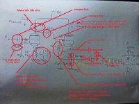
I made some edits using PAINT. Its not perfect but it will work.
The gain of the ECC88 is alreay at its max and I do get a mu = 30 with perfect signal up to 50 khz with everything excellent.
The Cat Fol is coupled via a cap (0,22 uF).
The Mosfets indeed have a Gate resistor (470). The bias system is : (+V)---4,7K----10K---10kadj---10k---(-V) and the gates take in on both sides of the adj 10K. This is standard and works. Comes from Broskie 's Tube CAD.
My current hybrid Mosfet has a much lower values bias system with a 1K between gates. Works beautyfully.
I have uploaded a (rather dirty but valid,) schematic of what I have now running in my current experiments. Please apologize for the bad quality !
I agree with the need for very low Zout, theoretically I should have it with the Cath Foll, but practically, far from it. Therefore my questions...
Thanks again !
Attachments
When driving the 3k load, the ECC82 has an open-loop gain of perhaps 5, and an open-loop output impedance of about 5.5k.
You have a 560k grid leak, and a 5k source impedance from the ECC88, so the feedback fraction is 5/(5+560) = 0.009.
The feedback factor is therefore 1+0.009*5 = 1.045
You should therefore expect the closed-loop output impedance of the ECC82 to be 5.5k/1.045 = 5.26k.
Lesson: The ECC82 is rubbish at driving a 3k load. You need an ECC88 or even a small power valve, and you need to use DC-coupling or fixed-bias to achive 100% feedback around the cathode follower.
 and you will need to raise those heaters when you use e88cc
The last time I used ecc82 was in a guitar amplifier 😉
Thanks DF96, now the formulas show every thing there.
And Frenchy Friend, don't forgot in rise the filamentary voltage. The cathode of the CF will be close to 90 volts, thats true the ECC88 was designed for use in cascode service but is as per usual.
And Frenchy Friend, don't forgot in rise the filamentary voltage. The cathode of the CF will be close to 90 volts, thats true the ECC88 was designed for use in cascode service but is as per usual.
Last edited:
Good morning to all,
So I have made the changes to a Direct coupling, removing the now unnecessary parts. I do get proper polarisations and a good output signal, unfortunately until a load of roughly 7K. Still very far from the less than 1K predicted theoretically.
the Zout I see appears close to the internal resistance of the valve... as if there was no gain no mu !
I will now lower the Rk value as suggested higher.
keep you posted.
Have a good day !
How did you measure it?the Zout I see appears close to the internal resistance of the valve...
How much signal amplitude do you need to drive the MOSFETs?
Yes, a CF can have low output impedance and poor driving ability at the same time. I'm not sure this is what is happening, though. Given previous experience in remote diagnosis my money is on the OP building a slightly different circuit to the one he thinks he has built!
Well, with a 10k fixed load to the Gnd , if I get half the signal at the output it should mean there is an impedance of the same amount in series before the load...
I need those 23 Vpk for the Mosfets.
Now what do you mean by having at the same time low impedance and poor driving ability ? is it the point where theory starts living on its own and not having anymore to do with reality ?
In fact this is exactly my question !
Thanks again
I need those 23 Vpk for the Mosfets.
Now what do you mean by having at the same time low impedance and poor driving ability ? is it the point where theory starts living on its own and not having anymore to do with reality ?
In fact this is exactly my question !
Thanks again
- Status
- Not open for further replies.
- Home
- Amplifiers
- Tubes / Valves
- Cathode follower attenuates signal