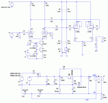
I'm slowly gathering parts for the amp described below but, considering how uncommon this topology is, I'm starting to wonder if I'm not doing something stupid. Thus, I really would appreciate any wake up calls or comments on this.
There is such a topology in the Tubecad software (see tubecad). It seems overly complicated for a true power amplifier but I'm tempted to use it for an headphones amplifier.
I've picked the ecl84 as cheap test tube. The pentode should do nicely as cathode follower, triode strapped, and the triode section has high µ, which is necessary to get sufficient gain from the amplifier. Good matching cannot really be expected from those tubes, so a ccs is used for the input ltp and some kind of trimmer must control the voltage at the grid of one of the outputs to balance the dc currents in the transformer (R16 being a 10k trimmer on the schematic).
I've also got a pair of 25W, 100V line transformers. They have 4-8-16 taps on the secondary and 400, 500, 800, 1600 taps on the primary. Using 300r headphones on the 16r secondary tap and the 400r primary tap as CT, it would translate into a 32K primary impedance (a 10X voltage ratio). But only 13K for 32r headphones on the 4r tap. The low impedance drive from the cathode follower should be useful to get a flat FR from the transformers at audio frequencies, especially considering that its inductance is pretty much an unknown.
PS: nevermind the PS, the second zener is there because my transformer is putting 30v too much. And obviously, the heaters must be raised to 100V or so.
Attachments
it would translate into a 32K primary impedance
It's doubtful that they have that much inductance.
In pentode mode Zout should be lower. I would use 6K4 load (1600:8 with 32R). In that case 10-15H will do fine. I think Pout will be limited by the RMS voltage provided by the triodes.
45
45
It's doubtful that they have that much inductance.
Duh... yes.
To see a bit the question of ratio I'd achieve, I've connected the transformer to the output of an headphones amplifier, driving 0.5V in the 1600R tap and common and grounding the CT (400R tap). On the other side, I connected a 470R resistor on the 16R tap (no 330 on hand). I got 180mV accross it.
Thus, that translates roughly into a total 5.5X voltage ratio (1V/180mV) and a 30X impedance ratio. The 300ohms headphones should be at around 9K, or am I still missing something ?
- Status
- Not open for further replies.
