I often see input stages and occasionally driver stages where no cathode bypass capacitor is used, either to control gain, or give a more favourable distortion spectrum.
Rarely, if ever, have I seen a single ended output stage with an unbypassed cathode resistor.
Why is this?
Is it simply a waste of output?
Is it the increase output impedance?
Recently, I completely re-jigged an amplifier I have been working on, and the configuration I ended up with, was no cathode bypasses, throughout all 3 stages of the amplifier, including the Output stage.
The performance was quite good, and stability/frequency response, was better than my last attempt at harnessing Global feedback - an attempt, which I thought was very promising, until I took a frequency sweep and saw a rising output, all the way to 75kHz!
Usually it is a waste of loop-gain when global NFB is used, but that doesn't mean you shouldn't try it! 😉Is it simply a waste of output?
That is not necessarily a big deal with pentodes since they already have high output impedance, but it could be undesirable in a triode output stage since it would potentially increase transformer distortionIs it the increase output impedance?
Last edited:
Well the valves are Soviet 6P6S, analogous to 6V6 and they were triode strapped.
I'm dealing with an OPT with multiple ultrasonic resonances, and no amount of fiddling seems to be able to optimise the Zobel across the secondary, without restricting the bandwidth far too much.
This isn't a huge problem, when I'm only using the local feedback; but it gets uglier, with my cludged together global loop is added.
Running all stages without cathode bypass capacitors, eliminates the peaking due to the global loop, and gives somewhat high(er) THD at max output.
Overall it looks like it may be the best compromise.
Some details about using this type of local feedback on a power pentode: Fundamentals Of Radio Valve Technique : Deketh, J : Free Download, Borrow, and Streaming : Internet Archive
Well, let's consider triode-connected 6P6S at the OP I personally would choose (Vp-k=320V, Ia=40mA, Vg=-22.5V).
Rk is about 560R.
For fixed bias or cathode resistor bypassed: ra=2.2k
For cathode resistor unbypassed: ra'=ra+(1+mu)*Rk=2.2k+(1+10)*560=6.16k
Rk is about 560R.
For fixed bias or cathode resistor bypassed: ra=2.2k
For cathode resistor unbypassed: ra'=ra+(1+mu)*Rk=2.2k+(1+10)*560=6.16k
I confess to having not printed out a characteristic graph, and plotting to find ra, at my op point.
(Va-k of 340V, Rk 560R, and Vg-k 24V)
But ra》3x is not...brilliant. I suppose though, that 6k isn't all that high.
Perhaps I should just persist with the Global loop, and try and wrangle the response back to flat? Maybe just use some different OPTs.
(Va-k of 340V, Rk 560R, and Vg-k 24V)
But ra》3x is not...brilliant. I suppose though, that 6k isn't all that high.
Perhaps I should just persist with the Global loop, and try and wrangle the response back to flat? Maybe just use some different OPTs.
Is it the increase output impedance?
Yes. I have a local friend who had an amp from a manufacturer I won't name, and it had a switch to switch out the cathode bypass cap on the output stage. We referred to that switch as the "bad sound" switch since the amp sounded terrible without the cap in there.
Just some random info:But ra》3x is not...brilliant. I suppose though, that 6k isn't all that high.
Attachments
I think I see what you're getting at TG..
But isn't the "Ra-a" listed the OPT impedance, and not the Ra of the valve itself?
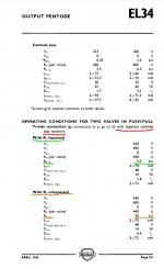
If I figure a 2k ra (from TG earlier bit of math), then bypassed the 6P6S isn't far from the EL34 data above, if I assume that the ra:Ra is about 1:3.
Of course, my situation is complicated by...plate to grid, not played to plate, local feedback to give about 3.5 to 4V/V gain.
So I have that degeneration, as well as the cathode😀
But isn't the "Ra-a" listed the OPT impedance, and not the Ra of the valve itself?
If I figure a 2k ra (from TG earlier bit of math), then bypassed the 6P6S isn't far from the EL34 data above, if I assume that the ra:Ra is about 1:3.
Of course, my situation is complicated by...plate to grid, not played to plate, local feedback to give about 3.5 to 4V/V gain.
So I have that degeneration, as well as the cathode😀
Last edited:
Ra-a is the load impedance indeed.
I just mean that leaving Rk unbypassed might work if you increase the load.
EL34's ra is about 1.1k and ra' is about 4.6k for the OP stated in the datasheet.
I just mean that leaving Rk unbypassed might work if you increase the load.
EL34's ra is about 1.1k and ra' is about 4.6k for the OP stated in the datasheet.
I always have 30-75ohm Rk on my 6AS7s. Have used over 100ohms also when many in parallel (they are not well matched).
The low mu means this is no issue, linearizes the output and limits thermal runaway. Most of my 6080/6AS7s run at roughly 10W plate and last for > decade.
If you are into the 'current drive' gang unbypassed Rks on tubes mentioned above posts is probably just good.
The low mu means this is no issue, linearizes the output and limits thermal runaway. Most of my 6080/6AS7s run at roughly 10W plate and last for > decade.
If you are into the 'current drive' gang unbypassed Rks on tubes mentioned above posts is probably just good.
I agree with SemperFi.
And if anyone is worried about wasting power, then get rid of tubes.
Examples:
A KT88 filament draws 1.6 Amps @ 6.3 Volts. That is 10.08 Watts, and still no B+, and still no music.
NPN no filament power required
PNP no filament power required
MOSFET no filament power required.
Do not get me wrong, I like tubes.
I use 5 tube amps, I only use one solid state amp.
I may just have to settle that I cant easily get 2W SET out of a 6P6S at 1% or less THD, without global feedback.
Since I've had such a nightmare trying to wrangle the response back flat when GNFB loop was added, with resonances at 25k, 50k, 75k and 100kHz maybe it's time to accept that using local feedback only, the best I can achieve is 2% THD.
Or make a headphone amp with the 6P6S and demand much less of them, maybe 1W at most.
Or accept, that maybe I should just build with 6P3S instead!
Here's an interesting observation:
If you increase the effective plate resistance with unbypassed cathode resistance, you do limit the available power, but you can recover the loudness by increasing the speaker magnet size - which ncreases efficiency but decreases the electrical Q of the speaker.
At one time, there were amps that used current feedback to obtain "unity damping" (ra=RL).
I may just have to settle that I cant easily get 2W SET out of a 6P6S at 1% or less THD, without global feedback.
I think you could easily achieve this with voltage feedback from the plate of the output tube to the cathode of the driver tube (like in my Corona amp). It's a short feedback loop and easy to stabilize. If you keep the OT out of the loop it makes things easy, and the OT doesn't add much distortion at midband unless you are pushing the limits.

If it's a dipping OPT resonance, increasing the stage output impedance will make it worse.
This truck only works for peaking resonances.
This truck only works for peaking resonances.
50AE & SS,
I am in truth not confident in which it is, but I suspect dipping.
It dips first, as I generally see HF rolled off anywhere between 22 and 44kHz, followed by decreased attenuation at resonant peaks, harmonics of the first dip.
Of course this initial roll off point slides about, depending on the primary load.
The OPT didn't suit being in the global feedback loop, I think 😀
The feedback was very effective, from inverted secondary to the cathode if the input stage.
But the frequency response was such that it made more like 3W at 100kHz, and 2W at 20kHz.
Using a RC om the OPT primary or secondary is also a waste of time, you still burn the power at 100kHz, you still strain the valves.
RC Low pass at the input works, but then it would...and I'm not going to have 100kHz input from music any time soon.
The only solution is to add a low pass in the feedback network, but this is not simple either it would seem! I got fairly close with something like 1k5 and 2nF in parallel with the feedback resistance.
I will have to revisit that set up, because it was 'the best' so far, if I recall HF started to roll off about 5kHz though a very gentle shelf to about -2dB at 18kHz.
- Home
- Amplifiers
- Tubes / Valves
- Cathode degeneration in Output Stage?