Good day all,
I am currently working on design of a PP class A amplifier (power monoblock) with KT88. Switching between UL and triode. Both modes output power max. 20-22W. Now is amp designed without NFB, but in the future I am thinking about introducing a weak NFB 5-6dB. I assume an input sensitivity of at most 1.4-1.5Vrms in Triode mode with NFB 5dB. In the UL mode, the sensitivity is lower. Input only balanced. In attachment is the schematics with assumed values. It is my first PP amp, before i designed only SE. I did not use LTspice when designing. I confess, I don't know how making simulations in LTspice. Until now I always used paint_kip/kit. I also used this program now.
Please, I want to ask you four questions (ranges of questions):
1) Do you think my design is okay? Or did I make some fatal mistake? What do you think of him? I want to avoid unnecessary expenses. And I want to achieve acceptable sound (i know subjective) with acceptable distortion.
2) What ccs do you recommend for Driver? LM334, or do you prefer cascode? Its no problem make a negative supply rail...
3) What ccs do you recommend for Power stage? LM317HV, or do you prefer cascode? I quite like the CCS in the attachment by Walt Jung.
4) Do you think that the ECC81 will be enough to drive the KT88? Either current or voltage? Or should I plan a two-stage driver? I prefer a minimal number of elements in the signal path. It looks fine on paper, but reality can sometimes be more complicated.
Unfortunately, I am not familiar with CCS and their designing and performance, so I am asking for your help with the design of this part of my amplifier.
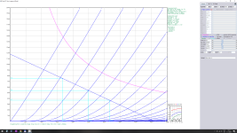
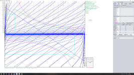
One more note (I don't know how important it is in the cathode CCS design, but I'll mention it just in case) max. HF for output transformer is 90KHz, and I want to make full use of this frequency band. I am also attaching the designs of the operating points ECC81 and KT88 UL.
Thanks for answers
I am currently working on design of a PP class A amplifier (power monoblock) with KT88. Switching between UL and triode. Both modes output power max. 20-22W. Now is amp designed without NFB, but in the future I am thinking about introducing a weak NFB 5-6dB. I assume an input sensitivity of at most 1.4-1.5Vrms in Triode mode with NFB 5dB. In the UL mode, the sensitivity is lower. Input only balanced. In attachment is the schematics with assumed values. It is my first PP amp, before i designed only SE. I did not use LTspice when designing. I confess, I don't know how making simulations in LTspice. Until now I always used paint_kip/kit. I also used this program now.
Please, I want to ask you four questions (ranges of questions):
1) Do you think my design is okay? Or did I make some fatal mistake? What do you think of him? I want to avoid unnecessary expenses. And I want to achieve acceptable sound (i know subjective) with acceptable distortion.
2) What ccs do you recommend for Driver? LM334, or do you prefer cascode? Its no problem make a negative supply rail...
3) What ccs do you recommend for Power stage? LM317HV, or do you prefer cascode? I quite like the CCS in the attachment by Walt Jung.
4) Do you think that the ECC81 will be enough to drive the KT88? Either current or voltage? Or should I plan a two-stage driver? I prefer a minimal number of elements in the signal path. It looks fine on paper, but reality can sometimes be more complicated.
Unfortunately, I am not familiar with CCS and their designing and performance, so I am asking for your help with the design of this part of my amplifier.
One more note (I don't know how important it is in the cathode CCS design, but I'll mention it just in case) max. HF for output transformer is 90KHz, and I want to make full use of this frequency band. I am also attaching the designs of the operating points ECC81 and KT88 UL.
Thanks for answers
Attachments

Last edited:
Interesting!
The input stage is not a phase inverter.
Instead it is a Balanced or Differential stage, because the signal to its grids is Balanced or Differential.
My tired, late night brain is not sure, but perhaps . . .
With the output stage which uses separate individual CCS for the cathodes . . .
The average current during peak music passages will not exceed the CCS quiescent current.
During loud music passages, as soon as the bypass capacitors run out of charge, the signal will soft clip.
Last edited:
6A3sUMMER:
Good night 🙂
I am familiar with the ccs function in this configuration. I don't even know what type of CCS to use. And I'm also not entirely sure whether the given circuit will work correctly, regardless of whether CCS is used in the cathodes. Try to imagine R/C in the cathodes in the drivers and the power stage. Of course, the driver will have a separate RC in the cathodes.
Thanks
"I don't even know what type of CCS to use"
The most critical value is the available voltage on the first stage cathodes: +3V
If you want to use such solution (CCS between cathodes and "ground"), only BJT can be considered as CCS.
Instead of this, I suggest to use negative voltage (12...20V) for CCS "negative" point, so wider variety CCS will be usable.
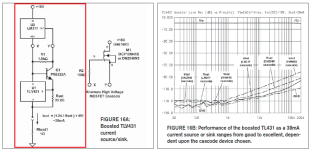
The output stage looks a little like this Tubecad idea:
For what it's worth Eli recommended ECC81 run with 200V on anodes and 3 mA per tube as a "sweet spot", but YMMV.
What is R9/C3 for? Some kind of active PSRR improvement? I don't think I've seen that before.

- Dual CCS to allow unmatched tubes (different DC on cathodes, but cathodes AC coupled through capacitors)
- 1M resistor at capacitor junction to provide a DC bias across each capacitor
- zeners to prevent cathode voltage rising during sustained bursts of high power, shifting the bias point
- Capacitor/10k resistor/diodes (missing from your circuit) softens the transition when the zener conducts
- Broskie usually shows LM317 based CCS for output stages
For what it's worth Eli recommended ECC81 run with 200V on anodes and 3 mA per tube as a "sweet spot", but YMMV.
What is R9/C3 for? Some kind of active PSRR improvement? I don't think I've seen that before.
Thank you all for advices. I just got the book from Morgan Jones Valve amplifiers 4. edition.
CCS with BJT and FET for vacuum tubes applications are well described here. Various variants. I recommend for study.
tikiroo:
Yes, I was inspired by some things on tubecad pages. As for the ECC81, I chose the operating point with a higher current so that it was possible to control the input capacity of the output tubes and also my operating point has more gain. Also, according to the simulation, lower levels of higher harmonics appear... We will see the reality. R9/C3 is PSSR improvement.
Staticx,
and
euro21,
Using RC to ground in the cathodes of the drivers changes them to Balanced, Differential requires a single CCS, that is connected to both cathodes.
Most CCS that have one end at ground do not have enough voltage at the cathode to make them work.
It is a function of the CCS minimum working voltage (burden voltage). With balanced / differential signals at both grids, the parallel cathode voltages are not supposed to move when signal is applied to both grids.
The CCS voltage issue is even more difficult when you make the driver stage also do the phase inversion. Only one grid is driven, the other grid is at signal ground.
The parallel cathodes' voltage change is 1/2 of the driven grid voltage change. A CD player puts out 2.1Vrms, which is +3V to -3V.
I did use a BJT, emitter resistor, base stopper resistor, 1.7V LED, and resistor to run the LED as a reference voltage to the BJT base stopper resistor.
My design had the lowest burden voltage of any CCS I ever used.
Sometimes you have to provide a negative voltage on the bottom of the CCS (for single grid drive of a phase inverter).
OK 6A3sUMMER and all,
I understand. Thank you.
Now let's forget about ccs in the cathodes.
When you look at the schematics and screens of the operating points and look at the AC and DC conditions emerging from them. Is my design ok?
I understand. Thank you.
Now let's forget about ccs in the cathodes.
When you look at the schematics and screens of the operating points and look at the AC and DC conditions emerging from them. Is my design ok?
I did a bit of spice modelling and it all looks OK. Gain would be low if you weren't using a balanced input, but OK as is.
tikiroo:
Thank you very much for your willingness. And did you consider 5-6dB NFB (local) during the simulation? I will probably implement it in the future. Did you simulate both UL and T?
Thank you very much for your willingness. And did you consider 5-6dB NFB (local) during the simulation? I will probably implement it in the future. Did you simulate both UL and T?
I didn't look at NFB, and only modelled triode as I already had a similar circuit to use. Maximum output power was about 16W for 1V rms input. Output stage stayed in Class A.
I'll have a look at UL but need to set up a transformer with the right ratio.
I'll have a look at UL but need to set up a transformer with the right ratio.
tikiroo,
Push pull output stages that have individual CCS in the cathodes, are intrinsically Class A circuits.
A long sustained 30 foot organ pipe will take the charge out of the bypass caps, so the long term output stage cathode current will be limited; can not sustain Class AB for long periods.
Instead of CCS, individual self bias resistors with bypass caps will work well for Class AB.
Or, if it is desired to not need bypass caps; a single self bias resistor connected to parallel cathodes will work well for Class AB.
6A3sUMMER,
Class A only is what i want. KT88 operating point is designed only for class A. For AB is now too hot.
Class A only is what i want. KT88 operating point is designed only for class A. For AB is now too hot.
Some Class AB KT88s, can run cooler than Some Class A KT88s.
In terms of both measurement results, and sound characteristics . . . there can be lots of difference between Class A and Class AB.
That is especially true when there is no negative feedback around the output stage (No Global negative feedback, No Schade negative feedback, No Ultra Linear negative feedback, and I think No negative feedback to the output stage cathodes too).
Ultra Linear is negative feedback around the output tubes.
Triode wired Pentodes and Triode wired Beam Power tubes, in Class A versus Class AB have less differences of measurement results and sound results, when there is no other negative feedback.
Triode wired Pentodes and Triode wired Beam Power tubes are using output stage negative feedback (plate to screen).
Last edited:
6A3sUMMER,
I plan switching between Triode and UL and with and without local NFB (CFB). It should bring different variations in distortion and also in damping factor.
I'm a little worried if my operating point for the KT88 is not too hot, when the mains voltage can fluctuate +-10%.
Also, I am concerned that the Uak of ECC81 may rise to a too high value (design center maximum = 300V) when the double triode sections are mismatched and if the supply voltage is 10% higher.
Last edited:
Staticx,
Slovakia?
I always use JJ tubes whenever possible.
I drive over to Eurotubes.com (near to me). They do extensive re-testing of the tubes that they get from JJ.
A phase splitter that uses only one driven grid, cathodes directly connected together to a single CCS, identical plate load resistances, and good non-gassy tubes . . .
Has Intrinsically Balanced signal swing amplitudes of the two phases.
But that has been discussed in way too many threads of Tubes/Valves; so lets not add comments here about that.
Your circuit which uses Balanced signals, and with the cathodes tied together to a single un-bypassed CCS, then the balance is also Intrinsic.
I am very fortunate at my location, my power mains only varies from 117VAC to 123VAC.
That is only + 2.5% to - 2.5%. Good!
I use a resistor to get 6.3V for the filaments, when the power mains voltage is centered at 120VAC.
I use choke input B+ filters, or modify that with a very low capacitance in front of the choke, to get the B+ voltage I want, again when the power mains are at 120VAC.
Last edited:
6A3sUMMER,
Yes Slovakia. I use only one time JJ tubes - KT77 in my SE-UL amp. And i was not satisfied. The music was not as detailed as I expected. As if I heard her through the blanket. When I used the EL34 Psvane special edition, it was a brutal difference. Maybe someday I'll try JJ small triodes. Are you satisfied with them?
As for the balance in splitter: It is clear to me that the AC balance will be perfect. I'm worried about the DC balance. If the current is greater through one section and less through another (single CCS), this will also affect the Uak of each section. It depends on how big the imbalance is.
In Europe is possible voltage deviation +-10%. And when I want to operate the amplifier in different places, it is necessary to take into account this deviation.
I looked at UL operation and it is pretty ugly above ~20W when the zeners start conducting, unless you bypass the CCS/zeners with capacitors like in the Tubecad diagram in post #5. Even before the zeners conduct, adding the bypass capacitors significantly reduces distortion and increases power. On the contrary for triode operation you get more power and lower distortion without the bypass capacitors. So maybe a triode/UL switch isn't such a good idea.
tikiroo,
Thanks for the simulation. The amplifier will be used only in pure class A. That means up to approximately 20W-22W. Distortion above 20W does not interest me. It will be used with sensitive speakers (over 95dB), this means that I will have sufficient power reserve.
Pleas can you chceck in simulation UL and Triode mode with 6dB NFB (CFB)? I am interested in what the input sensitivity will be at maximum power - before the large distortion.
- Home
- Amplifiers
- Tubes / Valves
- Cathode CCS based PP amp KT88