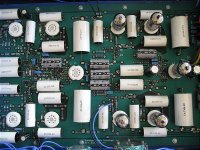
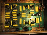
Since you already have a board, there's no need to worry about "board-level" changes. You'll be fine as is. Of the two series'd output resistors, the first could be made smaller if needed, maybe half, and the second could be replaced with a jumper. Not a big deal either way.
You'll be fine. Enjoy.
All good fortune,
Chris
You'll be fine. Enjoy.
All good fortune,
Chris
Hi all
I already tested the board as is and this are the bad's and the good's
bad thing:
The board has too much gain, I had to lower 15db in the DSP module (DIY analog devices and AKM project as well) of my dac in order to have some room with the volume control.
Good things
- I super happy with the tonal quality.
- The harsness of "ssss" in the voice is gone, in opera songs is incredible the diference with my rotel preamp.
- The soundstage is incredible
- the instruments separation is realy good
- Is super quiet
Can somebody sugest a improvement to correct the gain?
I realy like this preamp so I would like to fix this isuue.
Hello everyone,
Today I gave myself the task of doing some simulations in LTSpice of this diagram and experiment
I want to share what I managed to do, if somebody can give me feedback I'll appreciate it
This is the THD measurement of the original model and the output voltage,
original.jpg - Google Drive
This is the THD measurement of the improved model and the output voltage already with the reduced gain
Mejoras V4.jpg - Google Drive
This is the FFT graph of the original diagram
fft original.jpg - Google Drive
This is the FFT graph of the improved diagram,
FFT Mejoras V4.jpg - Google Drive
This is the frequency response of the original diagram
FR Original.jpg - Google Drive
This is the frequency response of the improved diagram
https://drive.google.com/file/d/1kbm0NBbARbIeyMvYV_8T8dYwSCa2q3Ag/view?usp=sharing
Hello
The first thing is to apologize for my English,it has a long time since I use it and surely something will write it wrong
As well as Avelasco, I am also riding a clone of SL-1,and I would apreciate if you could help me solve doubts
That I have the circuit that I am riding is very similar to the one that is riding Avelasco, but the schema is somewhat different and has some components of diferent value,I leave a copy of the schema whit the values that I am assembling ,I have mounted those that come printed on the PCB
In red I have indicated the value that I have mounted .
I would appreciate if you could tell me if these values are correct.
The other doubt I have is that potentiometer installed to regulate the volume, 50K or 100K
Greetings and thanks
Attachments
- Home
- Amplifiers
- Tubes / Valves
- CAT SL-1 clone DIY project

