I've just came up to an idea about cascodes, precisely about some threat in circuits with casodes, like cascoded voltage amplification stages or cascoded current sources.
I feel there is a lack of theory concerning cascodes, namely there is no explaination why cascodes don't always sound better, despite of technical advantages (reduced Early effect and Miller effect).
Some just state, that simpliest circuits sound best with no further technical explaination, others prefer cascodes because of theoretical advantages disregarding real listening tests.
The only technical drawback being an ultra high output impedance.?? I don't believe this matters so much.
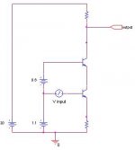
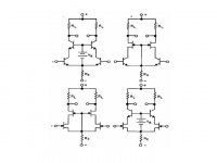
For start I attatch cascoded voltage gain stage to visualise.
to be continued...
I feel there is a lack of theory concerning cascodes, namely there is no explaination why cascodes don't always sound better, despite of technical advantages (reduced Early effect and Miller effect).
Some just state, that simpliest circuits sound best with no further technical explaination, others prefer cascodes because of theoretical advantages disregarding real listening tests.
The only technical drawback being an ultra high output impedance.?? I don't believe this matters so much.
For start I attatch cascoded voltage gain stage to visualise.
to be continued...
Attachments
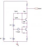
Now, reduction of capacitive negative feedback known as miller effect is considered the greatest advantage of cascode.
And the only band-limiting phenomenon is lowering current gain of a transistor with rising frequency, finite ft.
Needless to say modern audio transistors have very high ft, in range of hundreds of Mhz.
But things become look complicated when one considers in-built capacitances of active devices, frequency limits are so high, that these capacitances start to be significant.
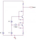
First glance-...yes, the common base stage has significantly capacitive load at emitter. Warning!!
to be continued...
And the only band-limiting phenomenon is lowering current gain of a transistor with rising frequency, finite ft.
Needless to say modern audio transistors have very high ft, in range of hundreds of Mhz.
But things become look complicated when one considers in-built capacitances of active devices, frequency limits are so high, that these capacitances start to be significant.
First glance-...yes, the common base stage has significantly capacitive load at emitter. Warning!!
to be continued...
Attachments
I don't state that all the cascodes are oscilators of course. But surely they may suffer from RFI, RF noise amplification, RF ringing and so on...
They also create complex eigenvalue (linear transfer function) with poles and zeroes and mad phase shifts at RF, thus feedback systems with cascodes may be significantly hard to stabilize.
Even if the whole system is stable internal parts may be ringing, which no good in audio, because of intermodulation.
Maybe no capacitive feedback (Miller effect) believed biggest advantage is actually biggest fault?
Your opinions?
Be merciful please. If what's above is utter ******** just forgive the offence of logic. Anyway it is worth trying to think and seek solutions, even wrong 🙂
best regards
As with everything, cascodes are neither good nor bad inherently, it's how you use them that's important. If you just go around cascoding everything willy-nilly of course you will end up with something that performs unpredictably. Add them where they address a specific need.
I don't recall ever seeing a cascode oscillate on is own as you theorize it might, but of course they do add phase shift and so may cause an amp as a whole to become unstable. A base stopper resistor and good PCB layout would alleviate the problem if it came up.
I don't recall ever seeing a cascode oscillate on is own as you theorize it might, but of course they do add phase shift and so may cause an amp as a whole to become unstable. A base stopper resistor and good PCB layout would alleviate the problem if it came up.
darkfenriz said:I don't state that all the cascodes are oscilators of course. But surely they may suffer from RFI, RF noise amplification, RF ringing and so on...
They also create complex eigenvalue (linear transfer function) with poles and zeroes and mad phase shifts at RF, thus feedback systems with cascodes may be significantly hard to stabilize.
Even if the whole system is stable internal parts may be ringing, which no good in audio, because of intermodulation.
Maybe no capacitive feedback (Miller effect) believed biggest advantage is actually biggest fault?
Your opinions?
Be merciful please. If what's above is utter ********just forgive the offence of logic. Anyway it is worth trying to think and seek solutions, even wrong 🙂
best regards
make a comparison between the two. from just throwing in parts, i think you'll find that the CE amplifier also has wiring parasitics, also has a bias current, ect... in the end you can simplify both to the same circuit...
without looking at numbers, and only looking at unvalued models, well, its impossible to say what you're going to get. is L1 signifigant, or does the oscillator have a center frequency of 25Ghz? if you really wanted to blindly simplify things to make things worse, you could add in distributed effects.
darkfenriz said:I feel there is a lack of theory concerning cascodes.........
Abidi, A. A., ‘On the Operation of Cascode Gain Stages’, IEEE Journal of Solid-State Circuit,
vol. SC-23, No. 6 pg. 1434, December 1988.
Jaeger, R., et al ‘On the Performance of the Differential Cascode Amplifier’, IEEE Journal of
Solid-State Circuit, vol. SC-8, No. 2 pg. 169, April 1973.
Yes, very good topic !
MrEVIL
"A base stopper resistor and good PCB layout would alleviate the problem if it came up."
I tamed oscillating cascodes with base stopper.
A little experience : I made a constant current source biased by an LED. Then I wanted to cascode it. I added a second LED in series with the the first to bias the common base transistor. Oscillation ! I then replaced the second the LED with a 1 kOhm resistor, the current through it and through the first LED was about 3 mA. No more oscillation. A few days later, I saw this last scheme having been used by Morgan Jones for a constant current source in a valve amplifier.
~~~~~~~ Forr
§§§
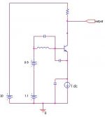
Darkfenriz:
Indeed, a cascode can behave like a Colpitts oscillator. The oscillation frequency can be very high (hundreds of MHz), which makes this not so easy to spot unless you have the right equipment. I reckon that this is one reason why some posters claim that they don't like the sound of cascodes, not knowing that the circuit that they have built may possibly have been oscillating.
A stopper resistor is a good counter-measure, and in general, having too-low impedance on the base is risky practice. This can be a mine waiting to ambush the unwary, particularly if you are using a capacitor to shunt out the noise of a cascode bias reference. Sometimes you can get away with this, sometimes not. If you encounter problems, heavier load impedance on the output of the cascode can sometimes be of help.
I would like to point out that this is absolutely an issue of physical construction (PCB layout) as well as the schematic. The type of schematic that can be used without problem, and the types of oscillation countermeasures and phase compensation that are needed, can be different according to the individual builder due to the differences in structural practice and technique.
As I have mentioned on numerous occasions in the past, the schematic is only a rough guide to the circuit, the real circuit is what is on the circuit board, including lead inductances and various parasitics. To look at the schematic only is a recipe for potential trouble (or over-compensation).
It is important to be able to recognize when and how an innocent-looking circuit fragment can easily metamorph into a potential trouble-maker, given the non-obvious electrical elements which can be added by the physical structure of the circuit, or things like environmental RF.
My own philosophy is that the schematic and physical layout should be designed together - the schematic should be designed and modified in consideration of the physical layout, and the physical layout should be designed and modified in consideration of the schematic.
hth, jonathan carr

jcarr said:Darkfenriz:
Indeed, a cascode can behave like a Colpitts oscillator. The oscillation frequency can be very high (hundreds of MHz), which makes this not so easy to spot unless you have the right equipment. I reckon that this is one reason why some posters claim that they don't like the sound of cascodes, not knowing that the circuit that they have built may possibly have been oscillating.
[...]
hth, jonathan carr
Jonathan,
thanks for enlightening informations. When I tried to built up a Connoisseur style preamp many years ago, with lots of helpfull input from your side, this might be one of the reasons I failed. The other was using resistive loaded emitters in the folded cascode instead of using current sources.
While I know your feelings about Kaneda circuits, I think that these are less demanding for the DIY builder, when it comes to hit or miss.
best regards,
Hartmut from Munich
jcarr said:Darkfenriz:
Indeed, a cascode can behave like a Colpitts oscillator. The oscillation frequency can be very high (hundreds of MHz), which makes this not so easy to spot unless you have the right equipment.
I reckon that this is one reason why some posters claim that they don't like the sound of cascodes, not knowing that the circuit that they have built may possibly have been oscillating.
I reckon that proves the adage:
If it measures right and sounds bad, then it isn't being measured right....
jcarr said:
I would like to point out that this is absolutely an issue of physical construction (PCB layout) as well as the schematic.
The PCB=The hidden schematic...
I often see cascode (so called by their authors) differential input circuits having the biasing voltage of the common base transistors referenced to ground. Used within a non-inverting amplifier, I wonder what kind of benefit could be attended from such a configuration.
To me, in a cascode, the biasing voltage must be referenced either to the base or the emitter of the common emitter transistor. In a differential pair with degenerative resistors in the emitters, it can be clamped to the common node of these resistors.
I am now speaking with reference to Linesource's image and only about bipolar circuits. I have seen two ways to clamp the reference to the above common node.
The first way uses an upper constant current source to bias the voltage reference, Vb. The lower constant current source then handles the current flowing through the cascode transistors AND the current delivered by the upper CCS flowing through the voltage reference. So the lower CCS has to handle quite a lot of mA.
The second way uses a PNP follower whose base is connected to
the common node of the differential emitter resistors. The emitter of the follower can be loaded either by a resistor or a CCS connected to the positive power supply, and the voltage reference is inserted in its emitter. Then, the lower CCS handles only the current through the cascode circuit, but I think the parasitic capacitor Cbc of the emitter follower may degrade HF performances.
I would prefer the first configuration, has it any other drawback than the one mentionned ?
Historicaly, the Linesource's upper right circuit has been used in the DB6 amplifier of DB systems (circa 1980). John Linsley-Hood used a single cascode - but with the grid of the fet connected to the base of the bipolar - in some of his mono-stage inverting phono preamplifiers (1978).
~~~~~ Forr
§§§
forr said:To me, in a cascode, the biasing voltage must be referenced either to the base or the emitter of the common emitter transistor.
Not really....working from first-principals, a cascode is a common-emitter stage driving a common-base stage....
Which means the later has its base at circuit 'common' (or 'ground') potential at the frequencies of interest....
Forr:
Regarding cascoding of input stages, it is OK to reference the biasing to either the base/emittor of the common emitter transistor or a fixed point. In some cases, referencing to the base/emitter can give additional improvements in measured distortion, but frequently referencing the biasing to a fixed point is easier to implement and provides the majority of the benefits (subjective listening as well as objective measurements).
hth, jonathan carr
- Home
- Amplifiers
- Solid State
- Cascodes- the truth is out there...