Hi guys - before I let the smoke out testing it, comments.
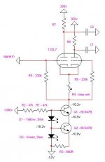
Note - no, its not a depletion mode device or any other format, I'm running with what I have here, so looking for confirmation that I'm in the ballpark with my figures (my first time specifying this schematic). I figure its around a megaohm of impedance anyway which is plenty for my purpose.
LED string should be passing around 3.5ma, ccs is set to 1.65ma or around that...
Attachments
looks good to go😉 What voltage will be at the Q1's collector? (In other wordds, beware not going over the transistor's Vc rating, which I'm sure you know...)
thanks semper - all things being equal, around 2Vdc. Its the common cathode of a 1st stage ltp.
Last edited:
aaaah true, but that's cheating - I don't learn as much...
OK, I cheated - negative rail advisable.
OK, I cheated - negative rail advisable.
Last edited:
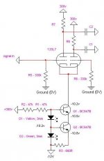
version 2.
The negative rail voltage is not a given - I have a bias supply I can draw from with up to -50v the practical limit.
I can't get my head around the biasing (I'm looking for -1.5v relative to the grid which results in 0.825ma idle per device)
- does the ccs automatically bias the devices, or, with the lowered negative rail, do I have to bias the cathode relative to signal ground using the variable resistor shown in the new diagram?
Attachments
Last edited:
- does the ccs automatically bias the devices, or, with the lowered negative rail, do I have to bias the cathode relative to signal ground using the variable resistor shown in the new diagram?
The tube will seek its bias, based on the current drawn by the CCS. Adjusting the resistor only changes the voltage at the top of the CCS, it doesn't change the grid to cathode voltage, and it requires a coupling cap on the input. It will bias that way, but there is no benefit.
Simpler to dispense with the variable resistor and connect your grid leak resistors to ground.
Sheldon
Yes and no, respectively. The pic below is more like what's needed. Some random thoughts:- does the ccs automatically bias the devices, or, with the lowered negative rail, do I have to bias the cathode relative to signal ground using the variable resistor shown in the new diagram?
If there's no input to the right triode, it's grid can be connected to ground. R6 will just add noise. R3 could be a trimmer if you want to adjust the current. The LEDs could be biased with a resistor to ground, saving a bit of current draw on the +300V line.
Attachments
thanks godfrey - that's the other diagram that I discarded in an effort to complicate my life further!
I thought about getting the LED bias from 0v, but I have the 300v close by, and its only supplying the 12sl7 anodes, so its not under a lot of stress! In fact, I hope that the added current through the LEDs will assist in stablising the 300v supply a bit.
Thanks for the suggestions and help everyone.
- Status
- Not open for further replies.
- Home
- Amplifiers
- Tubes / Valves
- cascoded bjt ccs - design check please