Haha, I didn´t credit anyone, only said I found it when googling  !
!
Any way this is the test from which I nicked it:
http://www.tnt-audio.com/ampli/aqvox_phono2ci_part2_e.html
If I understand it right, I think Werner Ogiers should be credited!
!Any way this is the test from which I nicked it:
http://www.tnt-audio.com/ampli/aqvox_phono2ci_part2_e.html
If I understand it right, I think Werner Ogiers should be credited!
I have to weigh in and say that I've used Allen's SuperReg and was VERY pleased with the result (exspecially ater trying his "current" mod on the original circuit-thanks Allen). If you have something new up your sleve with the AD811, drop me an email.
I have just tried the Janus Shunt reg and like it also (see tubecad.com)-but only the ss version, not the tube. I agree with Allen about drift when using a tube design.
I'm investingating Salas's shunt reg design to see if it will work for HV, but have not been able to find a P-Channel Mosfet able to handle the HV needed-but still looking.
revintage said:Hi Salas,
If we take it the other way around and accepts the 3,18uS constant and use the old school RIAA you would instead get -6,8dB at 100kHz. If we stay inside the 20-20kHz band the difference will be less than 0,5dB between the two at 20kHz.
Wouldn't be better to just extend flat? Rising at that high can create problems, especially with feedback loop circuits.
I cannot speak for your simulations, but the extra time constant DOES extend the bandwidth flat.
The peak you are seeing in your sims is in RELATION to the normal RIAA curve which decends from the 75uS point and keeps descending forever! It just looks like a peak on the screen.
The 3.18 extra TC just causes that decent to flatten out - no peaking in any circuits I've used it in, and I've been using it since 1975, over 30 years!
Regards, Allen (Vacuum State)
cygnus x1 said:I'm investingating Salas's shunt reg design to see if it will work for HV, but have not been able to find a P-Channel Mosfet able to handle the HV needed-but still looking.
We can see it in to using N-Channel if it proves we don't find any suitable P-Mosfet. Let me know.
Allen Wright said:I cannot speak for your simulations, but the extra time constant DOES extend the bandwidth flat.
Regards, Allen (Vacuum State)
jackinnj can maybe tell us more, if he sees this thread. He originally noted the peaking. Its nice that generally extends flat in your extended experience.
I also used the 3.18us time constant BUT that was on a mixed passive active RIAA using an opamp. It made a significant difference to the sound.
I've since retired that Phono Pre and am using a jLTi unit of Joe R's which was a step up.
Allen's FPV5A is on the list of next projects, so it will have it in.
Cheers,
Ian
I've since retired that Phono Pre and am using a jLTi unit of Joe R's which was a step up.
Allen's FPV5A is on the list of next projects, so it will have it in.
Cheers,
Ian
Did some simming yesterday to see if it could get any better. This way I reached 36dB gain and an overload margin of ca 50mV, 1kHz, 1% THD.
Will not build it, even if it looks quite nice on paper!
An externally hosted image should be here but it was not working when we last tested it.
Will not build it, even if it looks quite nice on paper
!Salas,
If you look at it logically, any peaking must be an error, either circuit, wiring or measurement.
Assume a very high frequency, then the impedance of the two caps in the RIAA network have gone to zero, and the network is now effectively just the "3.18uS" resistor.
That, in a NFB loop or in a passive divider, should/must result in a flat response.
Think about it...yes? No?
Regards, Allen (Vacuum State)
Allen,
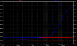
What Salas mean, is when you feed a "Neumann-compensated" RIAA with the unrealistic Lipshitz inverse RIAA, you get a in the ballpark of +6dB higher level at 100kHz.
It should ideally be no peak as the Lipshitz flattens out at 337kHz insted of 50kHz for the Neumann.
Probably the circuit tested had a limited bandwith that made it look like a peak at 100kHz frequency.
A thought: Neumann have a first or second order filter at 50kHz. Couldn´t Neumann then have a compensated RIAA correction to comply with the original RIAA curve between 20-20kHz. Has some actually tested this? This is only of academic interest as any serious audiophile should adjust his RIAA in combination with a testrecord(are there any reliable) and turntable to have straight frequency response at the RIAA output. Or?
revintage said:Allen,
What Salas mean, is when you feed a "Neumann-compensated" RIAA with the unrealistic Lipshitz inverse RIAA, you get a in the ballpark of +6dB higher level at 100kHz.
Lars, good point.
cygnus x1 said:I'm investingating Salas's shunt reg design to see if it will work for HV, but have not been able to find a P-Channel Mosfet able to handle the HV needed-but still looking.
I came up with a 500V easy to source N-Mosfet idea, check your e-mail.
My new phono preampl.
So you wanted to show, you don´t give a damn about the 4th constant
?Lars,
>What Salas mean, is when you feed a "Neumann-compensated" RIAA with the unrealistic Lipshitz inverse RIAA, you get a in the ballpark of +6dB higher level at 100kHz. <
I did understand that, and was trying to communicate exactly that.
But you don't get a peak in reallife, just more life in the music!
REgards, Allen (Vacuum State)
audiodesign said:
Very similar to what I'm doing except that I use CCS plate loads and LED bias to avoid cathode bypass caps. The D3a works astonishingly well- low noise, lots of gain.
Salas:
I just use LaPlace Transform for the RIAA and Inverse RIAA functions. With Multisim there is a "Transfer Function" block -- you just have to multiply the time constants together.
The method is described in Walt Jung's "Op Amp Applications" -- and you can probably find the chapter on Analog Devices website.
- Status
- This old topic is closed. If you want to reopen this topic, contact a moderator using the "Report Post" button.
- Home
- Amplifiers
- Tubes / Valves
- Cascode RIAA