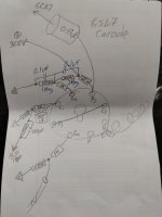
I'm modding my front end into a Cascode configuration and intend to bias G2 with a potential divider...
In his hi-fi Preamplifier book, Blencowe mentions that by omitting the screen grid bypass cap (Cg2) on the lower resistor of the potential divider we can allow PS noise into the screen grid as a NFB, which then increases the PSRR substantially.
Anyone tried this?
Does it affect the sound quality in any way?
I can't find this hack mentioned anywhere, only his book.
His valve wizard site omits this hack in its otherwise copied cascode chapter.
The Valve Wizard
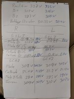
I just did a sim:
B+ ripple at the stage 2.2mV
G2 cap ground(normal) 1.7mV ripple
G2 cap removed 1.1mV ripple
Use 2 G2 caps, 1 ground, 1 to B+ 0.6mV ripple
Bad sound? I alsowant to test later at the moment my OTL got some hums maybe 2nd harmonics 120/100 hz
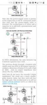
Reference: https://tubecad.com/2016/07/29/Cascode%20Amplifier%20with%20Restored%20Aikido%20Mojo.png
B+ ripple at the stage 2.2mV
G2 cap ground(normal) 1.7mV ripple
G2 cap removed 1.1mV ripple
Use 2 G2 caps, 1 ground, 1 to B+ 0.6mV ripple
Bad sound? I alsowant to test later at the moment my OTL got some hums maybe 2nd harmonics 120/100 hz
Reference: https://tubecad.com/2016/07/29/Cascode%20Amplifier%20with%20Restored%20Aikido%20Mojo.png
Thanks for replying..
I tried this on my LTspice model but can't see any difference with or without the cap. Ripple looks identical on the plate resistor, the screen grid and cathode.
I tried this on my LTspice model but can't see any difference with or without the cap. Ripple looks identical on the plate resistor, the screen grid and cathode.
This is one of those things IMHO you just have to try and listen to (easy enough to do). It could change the way it sounds? Might also affect the gain? No idea sorry. In my messing with cascode designs, I just left it in. If you want to reduce ripple/hum, I'd focus on PS filtering as that ends up everywhere, especially in an SE amp.
I connect another cap from g2 to B+, the buzz is still there, but no change to the sound that I can detect. The caps are for bypassing ripple hum if any, my case the buzz is coming from the RCA input, loud if I turn off the CD player, so those caps are really only necessary when is B+ is dirty.
Ps btw I just remember for real Pentode mode g2 should be bypassed (make reference) to the cathode, in the cascode, the cathode of the bottom triode, I try in sim, output level increase a bit, not much, don't how sound may changed.
Ps btw I just remember for real Pentode mode g2 should be bypassed (make reference) to the cathode, in the cascode, the cathode of the bottom triode, I try in sim, output level increase a bit, not much, don't how sound may changed.
Last edited:
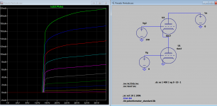
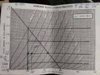
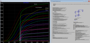
The plot is done by using Ltspice freely download from Linear Technology.
LTspice Simulator | Analog Devices
Beside software download and installation, tubes model files are also required for building the simulation files to run the plot sweep or other functions. I built models for Diyers, they can be used for other Spice family software too. The simulation file has .asc extension and is often passed around for sharing without also passing many files associated with it since it's already installed in you pc.
I've used LTspice for quite a while now and have tube models installed.
However I didn't know we could display their plate characteristics like that.
What's the procedure?
However I didn't know we could display their plate characteristics like that.
What's the procedure?
This is one of those things IMHO you just have to try and listen to (easy enough to do). It could change the way it sounds? Might also affect the gain? No idea sorry. In my messing with cascode designs, I just left it in. If you want to reduce ripple/hum, I'd focus on PS filtering as that ends up everywhere, especially in an SE amp.
Ok, Stephe - just waiting on parts..
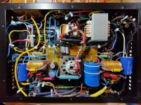
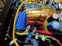
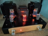
Completed!
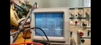
Well, I've done it.
I ended up trying John Broskie's "Akido Mojo" Cascode enhancement at am attempt at improving the inherent poor PSRR of this configuration with good results, ie, adding another cap across the top resistor of the potential divider feeding G2.
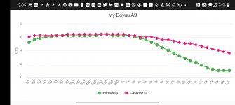
Got a much flatter frequency response with an extended top end.
Overall power output has increased compared to the original parallel configuration - now at just under 6Wrms per channel.
Very happy with the results!
Thanks to all!
Well, I've done it.
I ended up trying John Broskie's "Akido Mojo" Cascode enhancement at am attempt at improving the inherent poor PSRR of this configuration with good results, ie, adding another cap across the top resistor of the potential divider feeding G2.
Got a much flatter frequency response with an extended top end.
Overall power output has increased compared to the original parallel configuration - now at just under 6Wrms per channel.
Very happy with the results!
Thanks to all!
Attachments
-
 IMG_20210914_163842__01.jpg1,022 KB · Views: 171
 -
 IMG_20210914_163853.jpg982.9 KB · Views: 170
 -
 Screenshot_20210918-130618.jpg203.4 KB · Views: 183
 -
 Screenshot_20210918-130523.jpg276.1 KB · Views: 154
 -
 IMG_20210918_130736.jpg749.1 KB · Views: 90
 -
 Screenshot_20210914-173135.jpg545.7 KB · Views: 102
 -
 IMG_20210918_133249.jpg428.4 KB · Views: 104
 -
 IMG_20210918_133445.jpg396.8 KB · Views: 92
 -
 IMG_20210918_133825__01.jpg1 MB · Views: 84
Last edited:
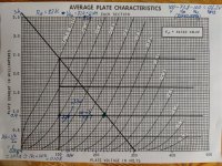
Whoa! How did you plot that in Spice?
How would you plot it "By Hand", without any magic tools?
Attachments
How would you plot it "By Hand", without any magic tools?
Ah, thanks.
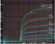
Which tube model you think is more accurate? If anyone has plotted the curve with tracer let's know thank in advance.
Attachments

Last edited:
From what I can tell, the second plot looks correct as the pseudo pentode's "knee* should be above Vg2.
Which tube model you think is more accurate? If anyone has plotted the curve with tracer let's know thank in advance.
In the second plot, it looks like the Ayumi model lines up closest to theoretical results. The others all seem to increase conduction gradually from well below the plate voltage of the bottom triode, which is not how the cascode curves are supposed to look. Interesting.
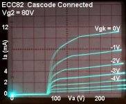
I pick another tube 12au7, they're better this time compared with trace here:
http://www.valvewizard.co.uk/Cascodegraph.jpg
http://www.valvewizard.co.uk/Cascodegraph.jpg
Attachments
- Home
- Amplifiers
- Tubes / Valves
- Cascode - Question about Cg2