I had a lot of fun this weekend playing with cascodes and I learnt some stuff:
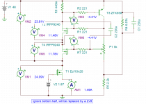
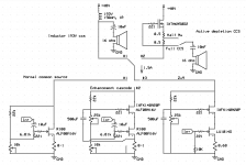
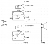
The schematics are pretty Zv9 but with the IRFP240 replaced with a IXFK140N20P. The CCS replaced by either a big fat inductor (Hammond 193V) or with a IXTH6N50D2 with 1 ohm degeneration (the simple Lamp CCS) where I can take output att full CCS at bottom or at half mu in the middle of the 1 ohm resistor. If wanted I can cough up the actual schematics but right now I am lazy 😛
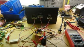
The PSU is a 48V 280W Desktop SMPS, works like a charm. The current on all amps is 1.5A so they all dissipate 75W. In the 193V variants I still run at 48V @ 1.5A, so more heat on the devices. This is why I selected the beast mosfet as it can easily handle my 70W expermient when cascoding a LU1014d with 193V CCS.
Cascodes are cool but might not always reduce distortion. With the R100 for example I got better performance without cascodes which isn't that far fetched as it performs better at higher voltages.
And lastly the LU1014d is a beast, as Nelson has shown us =)
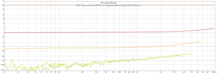
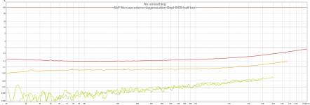
All measurements are with 16 ohm loads @1W.
My conclusions:
I will select the Zv9 to actually build. The 2nd harmonic is great as but there is a lot of 3rd. My guess is it might be due to the CCS not being ideal. With the 193V there is a clear lower bound distortion profile on odd harmonics and pretty much the same with the depletion CCS.
So the project for next weekend is CCS madness: I will compare the standard Zv9 CCS with a F2 CCS to see if a P-channel mosfet performs better. And when doing crazy stuff I might as well test to cascode the CCS too... as a simulation it seems to work OK. So if you know that it would be mega dumb feel free to steer me away from more dumbness 😉
The schematics are pretty Zv9 but with the IRFP240 replaced with a IXFK140N20P. The CCS replaced by either a big fat inductor (Hammond 193V) or with a IXTH6N50D2 with 1 ohm degeneration (the simple Lamp CCS) where I can take output att full CCS at bottom or at half mu in the middle of the 1 ohm resistor. If wanted I can cough up the actual schematics but right now I am lazy 😛
The PSU is a 48V 280W Desktop SMPS, works like a charm. The current on all amps is 1.5A so they all dissipate 75W. In the 193V variants I still run at 48V @ 1.5A, so more heat on the devices. This is why I selected the beast mosfet as it can easily handle my 70W expermient when cascoding a LU1014d with 193V CCS.
Cascodes are cool but might not always reduce distortion. With the R100 for example I got better performance without cascodes which isn't that far fetched as it performs better at higher voltages.
And lastly the LU1014d is a beast, as Nelson has shown us =)
All measurements are with 16 ohm loads @1W.
My conclusions:
- Molex micro fit jr connectors are very very nice when testing devices back and forth!
- As cascode device, the lateral Semelab ALF08N16V performs pretty much identical to the more muscular vertical mosfet IXYS IXFK140N20P. The IXYS has lower rdsOn though so I'm currently favouring it.
- The Hammond 193V is a really good CCS, at ~ 500 hz and upwards but less impressive below when compared to active CCS.
- For 16 ohm loads I get better performance with a full CCS than a half turn mu follower.
- The lateral ALF parts perform better without cascode. The R100 performs pretty much the same.
- Cascode modulation does absolutely nothing when cascoding the ALF or the R100. It does, however, work very well with the LU1014d.
I will select the Zv9 to actually build. The 2nd harmonic is great as but there is a lot of 3rd. My guess is it might be due to the CCS not being ideal. With the 193V there is a clear lower bound distortion profile on odd harmonics and pretty much the same with the depletion CCS.
So the project for next weekend is CCS madness: I will compare the standard Zv9 CCS with a F2 CCS to see if a P-channel mosfet performs better. And when doing crazy stuff I might as well test to cascode the CCS too... as a simulation it seems to work OK. So if you know that it would be mega dumb feel free to steer me away from more dumbness 😉
Attachments
Last edited:
Measurements!
Attachments
-
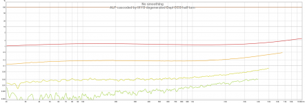
 10. ALF Cascoded by IXYS no degeneration Depl CCS half turn.png110.2 KB · Views: 127
 -
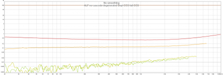
 9. ALF No cascode no degeneration Depl CCS half turn.png114.2 KB · Views: 110
 -
 8. ALF cascoded by IXYS degenerated Depl CCS half turn.png102.2 KB · Views: 122
 -
 7. ALF no cascode degenerated Depl CCS half turn.png112.7 KB · Views: 125
 -
 6. ALF no cascode degenerated Depl CCS full CCS.png111 KB · Views: 129
 -
 5. R100 cascoded by ALF & modulated cascode 193V CCS.png107.9 KB · Views: 111
 -
 4. R100 cascoded by IXYS & modulated cascode 193V CCS.png107.2 KB · Views: 115
 -
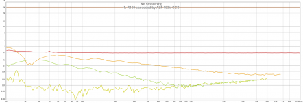
 3. IXYS no cascode 193V CCS.png102.5 KB · Views: 492
 -
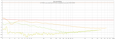
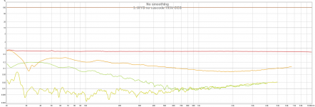
 2. R100 cascoded by IXYS 193V CCS.png105.7 KB · Views: 520
 -
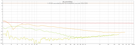
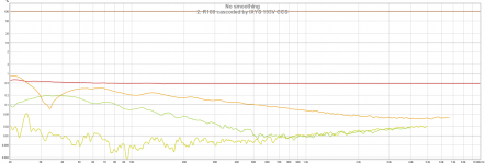
 1. R100 cascoded by ALF 193V CCS.png104 KB · Views: 566
More measurements!
Attachments
-
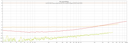
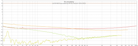 18. LU1014D Cascoded by IXYS a la Zv9 193V CCS.png109.3 KB · Views: 151
 -
 17. LU1014D Cascoded by IXYS a la Zv9 Depl CCS Full CCS.png115.8 KB · Views: 134
 -
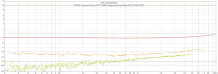 16. R100 Cascoded by IXYS with degeneration Depl CCS Full CCS.png116.6 KB · Views: 143
 -
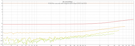 15. R100 No cascode with degeneration Depl CCS Full CCS.png120.3 KB · Views: 123
 -
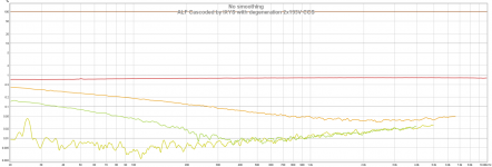 14. ALF Cascoded by IXYS with degeneration 2x193V CCS.png103.8 KB · Views: 120
 -
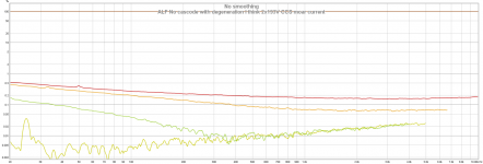 13. ALF No cascode with degeneration I think 2x193V CCS moar current.png111.8 KB · Views: 122
 -
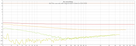 12. ALF No cascode with degeneration I think 2x193V CCS.png109.2 KB · Views: 151
 -
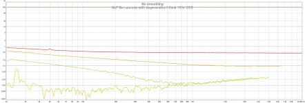 11. ALF No cascode with degeneration I think 193V CCS.png107.6 KB · Views: 145

They show combinations of those circuits at 1W into 16 ohm:
Not shown is that on all mosfets have back to back 9.1V protection zeners and the gate resistors differ for each device. The muscular IXYS for example has 22 ohm, the R100 100 ohm, the ALF 500 ohm, the LU1014d has 221 ohm and the depletion IXYS has 100 ohm.
Not shown is that on all mosfets have back to back 9.1V protection zeners and the gate resistors differ for each device. The muscular IXYS for example has 22 ohm, the R100 100 ohm, the ALF 500 ohm, the LU1014d has 221 ohm and the depletion IXYS has 100 ohm.
Attachments
Last edited:
show combinations of WHAT?They show combinations of those circuits at 1W into 16 ohm:.....................
show combinations of WHAT?
Described somewhat shortened and cryptically in the image descriptions:
The first for measurement is "1. R100 cascoded by ALF 193V CCS", so the bottom circuit is the middle with SJEP120R100 as gain device, ALF08N16V as cascode with the 193V as CCS.
The next measurement "R100 cascoded by IXYS 193V CCS" is identical but with the lateral ALF swapped with the IXFK140N20P.
The no cascodes are the leftmost bottom circuit, pretty much an F2 but with swapped gain device and CCS.
The "Full CCS" "Half mu" is when the active IXTH6N50D2 CCS is used, where Half mu is when output is taken from the middle of the two 0.5 ohm source resistors and the full ccs is taken at the bottom of them.
Modulated vs not modulated cascode is on the middle "Enhancement cascode" but where input to the cascode device is taken directly from the source of the gain resistor vs from below the source resistor thus not keeping constant voltage as described in the Zen v9 article.
The Zv9 is the rightmost and I didn't try any variants of that one yet. When I have solved the 3rd harmonic problem I'll probably try to push it to 10W and then compare the IXYS vs a lateral ALF and see if they still perform the same.
3rd harmonic. Are you showing distortions?When I have solved the 3rd harmonic problem
What are the labels on the vertical scale?
What is the flat red line at the top? and again about half way down?
The horiz scal is labeld upto 20 with log scaling. Is that frequency?
3rd harmonic. Are you showing distortions?
What are the labels on the vertical scale?
What is the flat red line at the top? and again about half way down?
The horiz scal is labeld upto 20 with log scaling. Is that frequency?
Ooops, now I see what you mean... I guess some part of smart must be compensated by equal part of dumb 🙄
The graphs are all distortion measurements where the brown top is the 100% signal. Red is 2nd harmonic, orange is 3rd, forest green is 4th and lime is 5th.
Last edited:
If you are playing with cascoding devices you should try an IRF3711PbF as the bottom device. It is a very nice 20 volt (Vds) mosfet with a Triode character similar to a SIT, but enhancement mode.
With an IRF3711 you can use cascode-modulation for the same distortion-cancellation as in the original Zen v.9 article.
Cheers,
Johannes
With an IRF3711 you can use cascode-modulation for the same distortion-cancellation as in the original Zen v.9 article.
Cheers,
Johannes
I've been playing around some more, don't have any more graphs at the moment as I forgot to save them. Swapping the current source for the F2 IRFP9240 one does improve performance, it pushes the slow H2 increase upwards in frequency but at 200 hz they both perform the same.
At 1W it isn't that much a problem, the problem is that distortion is pretty ugly above 4W and the midwoofers I want to drive are fairly insensitive at 90 dB @ 16 (8+8) ohm.
So the current plan is to rewire them from 8+8 in series to parallel to get 4 ohm and then take a look at the F6 for more umph.
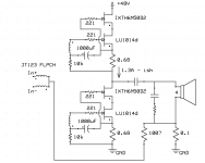
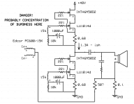
I keep thinkin about cascoding though... I measured my proto amp and my LU1014d's are all the same vgs (Thank you Deep Surplus!) and it just so happens that in the amp with 0.68R source resistor there is 1.5V across it. And it just happens to be that the IXTH6N50D2 conducts 1.5A at -1.5Vgs... So I will probably try something like this and see what happens, hopefully it biases up nicely and doesn't go up in smoke =)
The real problem, however is that I do not have any Jensen JT123 FLPCHs... yet... I do, however, have 2 Edcor PC600/15K. I might as well try something crazy for science and use both Edcor transformers as subsitute until I get the Jensens. In that case I'm not sure if I should keep the transformer to bottom of source resistors at 10k or up them to say 47k, I guess I'll have to try and find out what I should use.
At 1W it isn't that much a problem, the problem is that distortion is pretty ugly above 4W and the midwoofers I want to drive are fairly insensitive at 90 dB @ 16 (8+8) ohm.
So the current plan is to rewire them from 8+8 in series to parallel to get 4 ohm and then take a look at the F6 for more umph.
I keep thinkin about cascoding though... I measured my proto amp and my LU1014d's are all the same vgs (Thank you Deep Surplus!) and it just so happens that in the amp with 0.68R source resistor there is 1.5V across it. And it just happens to be that the IXTH6N50D2 conducts 1.5A at -1.5Vgs... So I will probably try something like this and see what happens, hopefully it biases up nicely and doesn't go up in smoke =)
The real problem, however is that I do not have any Jensen JT123 FLPCHs... yet... I do, however, have 2 Edcor PC600/15K. I might as well try something crazy for science and use both Edcor transformers as subsitute until I get the Jensens. In that case I'm not sure if I should keep the transformer to bottom of source resistors at 10k or up them to say 47k, I guess I'll have to try and find out what I should use.
Attachments
Last edited:
- Status
- Not open for further replies.
- Home
- Amplifiers
- Pass Labs
- Cascode madness