Does anyone out there have info for calculating the frequency response of a standard cascode stage? I figured out the Zo and all that, but I an sketchy on the low frequency cutoff from the capacitor in a partially bypassed cathode...and the high frequency rolloff from a grid resistor due to the input capacitances. I don't know how the cascode configration effects these parameters, or do I just follow the spec sheet for the tube (6922, etc)?
Why don't you post a schematic of the stage you have in mind, and we'll go through it bit by bit?
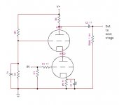
Here you go
If I can understand just a simple cascode like this one, then I can tweek it however. I can calculate grounded cathode triode stages in my sleep, but I am not sure how the cascode arrangement changes the tube's Cgk and Cgp for calculating the high frequency cutoff from the grid input circuit (R1).
i THINK the gain calculation is just the RP x transconductance. So I set my plate resistor to give a gain of 100. Assume V+ on the plate at around 300v or 350v or 250v or whatever.
The cathode bypass capacitor is a bit confusing. I THINK that to get the value of C1, I can just treat the bottom tube as a grounded cathode circuit and then do the math as per normal...eg. calculate the tube's cathode output impedance and put it in the 1 / (2*pi*Zk*C1). BUT I need to know the proper value of the cathode bias resistor to do that (R5) and I don't know who the cascode circuit effects the current through the tube.
Finally, the Zo... I am a little fuzzy on that too, and I would need that to calculate C2 for my low freq cutoff. I THINK it is just Zo = Ra || (mu + 2) rp, which would put my circuit here around 7.5K.
Thanx to anyone who can help!!
Attachments
I think I figured some stuff out
OK,
1) for the input capacitance for calculation hi's rolloff, just take the Cga of the tube, since the cascode configuration sheilds the math from the whole crappy Miller capcitance thing?
2) the resistive divider on the top tube's grid sets the plate voltage of the bottom tube?
3)The top tube does not alter the current in this configuration, so just draw a load line using the voltage at the top tube's grid as a function of slope against the desired plate current, and use ohm's law to get the value of the cathode resistor?
4) I was right about the gain formula and the output impedance formula?
WHEW! My brain hurts...If I am worng about this crap, someone let me know.
Thanx
1. Not quite. You still have Miller capacitance in the lower valve. You need to know the gain to the anode of the lower valve. Looking up from the anode, the lower valve sees your 8k resistor divided by (u+1). That's not going to be very much, so in your particular case, the lower valve has a very low gain to its anode - meaning that you probably can ignore Miller. Do the sums anyway - just for the exercise.
2. Yes. Plus Vgk of the upper valve.
3. Yes.
4. No. Rout is much higher than that. ra for the upper valve is modified and is equal to ra + rk.(u+1). rk for the upper valve is ra of the lower valve, and that makes ra for the upper valve rather large. A quick and dirty approximation is that rout for a cascode equals RL.
Those previous modifications mean that your approximation for gain is likely to be a little optimistic, but quite good enough for a "back of envelope calculation".
You are now in a position to find the frequency response because you know your input capacitance (and associated source resistance) and your output resistance (and associated load capacitance).
Thanx!!
Awesome! That helps a lot. I'll just rethink my source voltage and plate resistor to up the gain and reset the bias accordingly.
One last small issue. To calculate the output impedance for the bottom tube's cathode so that I can set the low cutoff in a partially bypassed cathode circuit due to C1.
THANX!
Cathode output impedance
I tried my hand at figurng the output impedance of the bottom tube.
2.6k + 2.6k * (33+1) = 91 add that to the 2.6k ra of the bottom half to get 93.6K
93.6K / (mu+1) = 93.6k / 34 = 2.84k ???
...which sounds wrong to me. If I used a 200 ohm cathode resistor, then in parallel, they would = 187 ohms. Put that in the formula 1 / (2*pi*190*Ck) with a value of 47u in Ck, that would mean the the low end amplification of the stage would roll off at 18Hz.
...if I ever get this all sorted out, I'm posting all the math with a diagram online for future generations to enjoy. The cascode is such a mystery to so many...
Your first equation gives ra for the upper valve, which as you've shown, is quite high. Now you know why the rule of thumb is that rout = RL.
If you want to know the output impedance at the anode of the lower valve, it's just ra in parallel with the resistance looking up into its anode circuit, so that's RL divided by (u+1) of the upper valve. That makes it fairly low.
The resistance looking into the cathode of the lower valve is a little lower than for a normal stage because RL for the lower valve is very low (RL of the upper valve divided by (u+1) of the upper valve).
Sweet
Thanx a lot man,
All of that is helpful. I think I have it all sorted out now. My fear of cascodes has subsided and now I am off to tweek. I think I'll take a stab at the TubeCAD recommendations for improving the circuit's abysmal PSRR. I guess building a quiet power supply always helps too 😉
Thanx a lot man,
All of that is helpful. I think I have it all sorted out now. My fear of cascodes has subsided and now I am off to tweek. I think I'll take a stab at the TubeCAD recommendations for improving the circuit's abysmal PSRR. I guess building a quiet power supply always helps too 😉
One more question about biasing cascodes
One last thing. In this configuration, do I set the bias point using the top triode's plate resistor as the plate load and the voltage at the bottom triode's anode as the V+, and then just plot my load lines accordingly? Or do I use the Full V+ at the supply node?
One last thing. In this configuration, do I set the bias point using the top triode's plate resistor as the plate load and the voltage at the bottom triode's anode as the V+, and then just plot my load lines accordingly? Or do I use the Full V+ at the supply node?
Yes, for the purpose of loadlines, treat the lower valve's anode as 0V, giving you a reduced B+.
THANX AGAIN
Thank you again.
So... as an example to make sure I have it, if I plot a 10K resistor with a power supply of 300v, which is voltage divided at the upper triode's grid to 100v, so we add like 2v for the top tube's Vgk so start loadline at 102v, then other end of the line is at 100v/10k=10mA?
Thank you again.
So... as an example to make sure I have it, if I plot a 10K resistor with a power supply of 300v, which is voltage divided at the upper triode's grid to 100v, so we add like 2v for the top tube's Vgk so start loadline at 102v, then other end of the line is at 100v/10k=10mA?
If you're plotting the upper tube's loadline, you'd look at the difference between the cathode voltage (that's roughly 102V, call it 100 for ease of arithmetic) and B+. That's a 200V differential. The load line then runs from the x-axis at 200V to the y-axis at 200V/10K= 20mA.
The lower tube's loadline will run from the x-axis at 100V to the y-axis at 100V/(10K/{mu+1}), again ignoring the Vgk. For an ECC88, that will look roughly like 300 ohms.
The lower tube's loadline will run from the x-axis at 100V to the y-axis at 100V/(10K/{mu+1}), again ignoring the Vgk. For an ECC88, that will look roughly like 300 ohms.
Good enough for jazz...
As SY says, the upper valve only has 200V, well, alright, 198V if you want to be finicky about it.
As SY says, the upper valve only has 200V, well, alright, 198V if you want to be finicky about it.
I steadfastly refuse to calculate that last decimal place. One equals two for large values of one.
Sorry to step in, I thought Nurse had already put you to bed.
Sorry to step in, I thought Nurse had already put you to bed.
YOU GUYS RULE!
Thanx so much for the help. I have been thinking about the cascode upside down and backward for years apparently.
One more question to verify that I have a handle on it, and I'll let this thread rest. I'm going to omit the abbreviation so that I don't get my terms crossed.
To calculate the freq response from a capacitor bypassed cathode resistor, we need to know the impedance looking into the cathode, which for a cascode means "plate resistor"/('tube gain'+1).
Then we just use:
-3dB point=1/(2*pi*"cathode capacitor value"*("impedance looking into the cathode"||"cathode bias resistor")
Am I cool there?
If I indeed have a handle on this, then I AM going to make good on my promise to put all this into one place for budding DIY'ers who are equally as clueless as I am to see and enjoy.
Thanx a million times.
Close. The looking-in impedance seen at the cathode is (plate resistor plus plate resistance)/(mu + 1).
Remember, the cap bypass doesn't do a cutoff, it just produces a shelf, and not a terribly big one in this case, either.
Remember, the cap bypass doesn't do a cutoff, it just produces a shelf, and not a terribly big one in this case, either.
Wait a minute!
WAIT! Wouldn't that produce a ridiculously high point on the y-axis to start out loadline from...like 300mA!? The chart obviously goes to only 20mA. Or do we use the top tube's load line to get the bottom tube's cathode bias resistor...grrr...I thought I had it, but then I lost it.
SY said:Close. The looking-in impedance seen at the cathode is (plate resistor plus plate resistance)/(mu + 1).
Remember, the cap bypass doesn't do a cutoff, it just produces a shelf, and not a terribly big one in this case, either.
WAIT! Wouldn't that produce a ridiculously high point on the y-axis to start out loadline from...like 300mA!? The chart obviously goes to only 20mA. Or do we use the top tube's load line to get the bottom tube's cathode bias resistor...grrr...I thought I had it, but then I lost it.
- Status
- Not open for further replies.
- Home
- Amplifiers
- Tubes / Valves
- Cascode gain stage info?????