One last question, if anyone has any insight, there's 2 mica caps (one per channel) bodged in between pin 3 (cathode) and R- (ground) on 1 of the 4 tubes per channel. Any idea why they would do that? It's only on one of the tubes, which seems odd to me.
I tried very hard to find that capacitor on any and all the schematics on this thread.
I could not find any mica capacitor (like a pF value, not a uF value) that was tied from any Pin 3 to ground.
Do these capacitors only exist on the real, physical amplifier you have; and Not on the schematic?
I could not find any mica capacitor (like a pF value, not a uF value) that was tied from any Pin 3 to ground.
Do these capacitors only exist on the real, physical amplifier you have; and Not on the schematic?
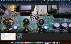
Exactly, they're right here. I'm trying to understand their purpose, it's like another bypass cap, but then why does only one tube on each side get one?Do these capacitors only exist on the real, physical amplifier you have; and Not on the schematic?
Attachments
Since they are not on the schematic,
Can you tell us how many pF they are, Please?
Since all 4 cathodes are only separated from each other by 20 Ohms (2 x 10 Ohms, from cathode to cathode), the mica cap effectively is across all 4 tube's cathodes.
Take them out, and you may end up with an oscillator instead of an amplifier.
Or, the designer may have liked to see people scratch there heads, trying to figure out why the cap is there.
My $0.02
They are marked 103J, so I'm guessing 0.01uF? I'll check it for real tomorrow, it's running right now 🙂Can you tell us how many pF they are, Please?