Hi Folks…
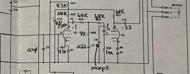
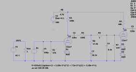
I had an early 90’s era Cary Audio SLP-70 preamp recently fully refurbed.. It is the Line version only without the Phono section on the PCB.. So I found the Phono schematic for it and had the board populated by a tech.. What do you guys think of the RIAA EQ Filter circuit of the All 12AX7 Phono section? Are those 1N4148 signal diodes on the cathodes of the 12AX7’s?
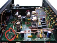
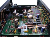
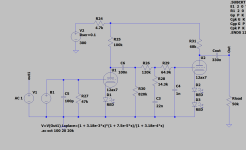
I attached a schema of the Phono stage section.. I have also seen on the net recent photos of latest revision of the said preamp, and the “C9” cap filter part of the RIAA EQ has been omitited and jumper wires were put in its place (check attached photo I found on the net with the Jumper Wire encircled in Red ..) I’m not sure if I have to omit C9 too, or just follow the schematic shown here.. So far to my ears, without the C9 (0.1uF), there is a lack of bass response.. I haven’t tried it yet with the C9 in place.
Any info you guys may share would be greatly appreciated..
I had an early 90’s era Cary Audio SLP-70 preamp recently fully refurbed.. It is the Line version only without the Phono section on the PCB.. So I found the Phono schematic for it and had the board populated by a tech.. What do you guys think of the RIAA EQ Filter circuit of the All 12AX7 Phono section? Are those 1N4148 signal diodes on the cathodes of the 12AX7’s?
I attached a schema of the Phono stage section.. I have also seen on the net recent photos of latest revision of the said preamp, and the “C9” cap filter part of the RIAA EQ has been omitited and jumper wires were put in its place (check attached photo I found on the net with the Jumper Wire encircled in Red ..) I’m not sure if I have to omit C9 too, or just follow the schematic shown here.. So far to my ears, without the C9 (0.1uF), there is a lack of bass response.. I haven’t tried it yet with the C9 in place.
Any info you guys may share would be greatly appreciated..
Attachments
C9's location can be jumpered, you only need one DC blocking cap.
The RIAA network values are wrong.
The RIAA network values are wrong.
Looks like a questionable implementation of passive RIAA correction. Diodes are LEDs.
Hi,
In the photo I attached here (without the Red circle) you could see near the 12ax7’s (3 in a row) that they are not Light Emitting Diodes.. They have bands, that’s why I suspected that they are signal diodes.. Thanks.
Attachments
C9's location can be jumpered, you only need one DC blocking cap.
The RIAA network values are wrong.
Oh, that sucks.. That schema is included in a Cary Manual (early version of the preamp w/out a CF output for the Linestage section).... Thanks for checking.. It would be great if someone knowledgable could calc the correct RC values for the RIAA network..
With a 12ax7 driving a passive compensation network, you're never going to know the correct values since the "rp" (anode resistance) can be over a very wide range. SY mentioned this in his article "His Master's Noise" which you can find in the "Articles" section of "Forums".
"rp" will also change over time as the tube ages. Here are some guesses
"rp" will also change over time as the tube ages. Here are some guesses
Attachments

Thank you very much!.. I’ll study your Spice sims and get back to you soon.. I guess it is imperative to use Red LED’s for optimum peroformance even if the original design called for different diodes..
Is R28's value 8kohm or 18 kohm? R28 times C7 should be 318 us, so with 22 nF, that would be 14454.545454... ohm, closest E12 standard value 15 kohm.
I did some calculations on a similar RIAA correction network with AC coupling on the input side. The AC coupling rather complicated the calculation, so I settled for a good approximation. See https://www.diyaudio.com/community/...a-calculator-formula-help.401437/post-7439558
I did some calculations on a similar RIAA correction network with AC coupling on the input side. The AC coupling rather complicated the calculation, so I settled for a good approximation. See https://www.diyaudio.com/community/...a-calculator-formula-help.401437/post-7439558
Last edited:
Assuming the 12AX7 has an internal resistance of 62.5 kohm including the effect of the impedance of the diode in the cathode, assuming C13's impedance to be small enough to be neglected and keeping all capacitors as is, my calculation finds these values:
C9 replaced with a short
R30 removed
Extra 820 kohm resistor to be placed from the right side of C6 to ground
R25 remains 100 kohm
R26 = 120 kohm E12 or 118 kohm E96 (theoretically 118.51317 kohm)
R28 = 15 kohm E12 or 14.3 kohm E96 (theoretically 14.454545... kohm)
R29 = 68 kohm E12 or 64.9 kohm E96 (theoretically 64.6913593 kohm)
C6 remains 100 nF
C7 remains 22 nF
C8 remains 1 nF
The reason why I suggest removing R30 and placing an extra 820 kohm from the AC coupling capacitor C6 to ground is simply that that's the way it was in the circuit I did calculations for. There is no reason why it would be better or worse than the variant with R30, but my calculations only apply to a circuit with the resistor to ground immediately after the AC coupling.
A red LED runs at about 1.8 VDC lit, so are a poor bias point choice for type 12AX7. Maybe try an IR diode at (lit) 1.2 VDC. The original regular silicon diodes would have sat at about 0.6 or 0.7 VDC, FWIW. None of these is even remotely linear, but they don't move very far in actual use. Nobody worries much about (single sided) electrostatic microphones.
All good fortune,
Chris
ps: if it's not lit, it's especially non-linear
All good fortune,
Chris
ps: if it's not lit, it's especially non-linear
Assuming the 12AX7 has an internal resistance of 62.5 kohm including the effect of the impedance of the diode in the cathode, assuming C13's impedance to be small enough to be neglected and keeping all capacitors as is, my calculation finds these values:
C9 replaced with a short
R30 removed
Extra 820 kohm resistor to be placed from the right side of C6 to ground
R25 remains 100 kohm
R26 = 120 kohm E12 or 118 kohm E96 (theoretically 118.51317 kohm)
R28 = 15 kohm E12 or 14.3 kohm E96 (theoretically 14.454545... kohm)
R29 = 68 kohm E12 or 64.9 kohm E96 (theoretically 64.6913593 kohm)
C6 remains 100 nF
C7 remains 22 nF
C8 remains 1 nF
The reason why I suggest removing R30 and placing an extra 820 kohm from the AC coupling capacitor C6 to ground is simply that that's the way it was in the circuit I did calculations for. There is no reason why it would be better or worse than the variant with R30, but my calculations only apply to a circuit with the resistor to ground immediately after the AC coupling.
Hello.. Thank you very much for the detailed explanation of the calculations you made etc, and the link to the pdf and zip files.. I really like to try this first as there is minimal outlay in parts.. I’m just trying to to think of a way to install the 820k R to GND without “mucking” the way the PCB was laid out..
Hello Marcel,
I am in no hurry.. Thank you very much for the offer to further help.. Keep safe..
I am in no hurry.. Thank you very much for the offer to further help.. Keep safe..
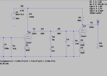
With Marcel' suggestions. (I had used Lipshitz 1c for the schematic I drew). I changed the designators to conform with the OP's drawing.
As I mentioned, the buildout resistor value R26 will vary with "rp".
As I mentioned, the buildout resistor value R26 will vary with "rp".
Attachments
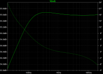
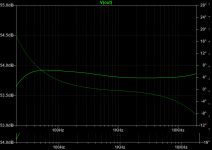
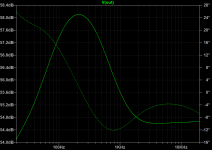
I found an approximate solution with the grid leak resistor at the end. It isn't quite as accurate as my earlier approximation with the grid leak resistor just after the AC coupling, but like Jack wrote, the first pole will not be super accurate anyway because of the inaccuracy of the internal resistance of the valve. If all resistances and capacitances were exactly as calculated, the error would be about 2 %, still less than 0.2 dB.
Again assuming the 12AX7 has an internal resistance of 62.5 kΩ including the effect of the impedance of the diode in the cathode, still assuming C13's impedance to be small enough to be neglected and keeping all capacitors as is, my calculation finds these values:
C9 replaced with a short
R30 remains 1 MΩ
R25 remains 100 kΩ
R26 = 150 kΩ E12, 130 kΩ E24 or 140 kΩ E96 (theoretically 139.71507245752 kΩ)
R28 = 15 kΩ E12 or 14.3 kΩ E96 (theoretically 14.454545... kΩ)
R29 = 68 kΩ E12 or 69.8 kΩ E96 (theoretically 70.6741409656935 kΩ)
C6 remains 100 nF
C7 remains 22 nF
C8 remains 1 nF
See the attachments, particularly chapter 4 of the pdf, for the derivation.
Attachments
I found an approximate solution with the grid leak resistor at the end. It isn't quite as accurate as my earlier approximation with the grid leak resistor just after the AC coupling, but like Jack wrote, the first pole will not be super accurate anyway because of the inaccuracy of the internal resistance of the valve. If all resistances and capacitances were exactly as calculated, the error would be about 2 %, still less than 0.2 dB.
Again assuming the 12AX7 has an internal resistance of 62.5 kΩ including the effect of the impedance of the diode in the cathode, still assuming C13's impedance to be small enough to be neglected and keeping all capacitors as is, my calculation finds these values:
C9 replaced with a short
R30 remains 1 MΩ
R25 remains 100 kΩ
R26 = 150 kΩ E12, 130 kΩ E24 or 140 kΩ E96 (theoretically 139.71507245752 kΩ)
R28 = 15 kΩ E12 or 14.3 kΩ E96 (theoretically 14.454545... kΩ)
R29 = 68 kΩ E12 or 69.8 kΩ E96 (theoretically 70.6741409656935 kΩ)
C6 remains 100 nF
C7 remains 22 nF
C8 remains 1 nF
See the attachments, particularly chapter 4 of the pdf, for the derivation.
Hello Marcel,
Again, thank you👍🏼!! It’s interesting to know that the C13 B+ decoupling cap’s impedance could affect RIAA accuracy that much.. I actually have 47uF Nichicon PW’s (Low ESR) in that position..
The new resistor values aren’t difficult to source (precision low noise types..)
Thanks again!
Thanks to all who contributed in this thread..
That 2 % error is due to an approximation I used to simplify the equations. I don't know how much influence the impedance of C13 has, but it should be very small. When you leave it out altogether, you get a bypass via R25, R24, R31 that shouldn't be there.
I'm probably stating the obvious now, but if you can get them, it's best to use the E96 values and forget the E12/E24 values.
I'm probably stating the obvious now, but if you can get them, it's best to use the E96 values and forget the E12/E24 values.
Last edited:
- Home
- Amplifiers
- Tubes / Valves
- Cary Audio Preamp Phono Section (SLP-70)