I finnally fixed my carver brick, i love this amp, ever since i sold my old 1200 i was sad all the time, i finnaly got my hands on a 1.5 wich is actually the same thing....well i think, i remember my 1200 having 1.5a boards in it, Anyways my problem is quite simple, on my 1200 i had gotten rid of the power down sound it made with an "upgraded" board i had gotten from a service center, and also they had sent me a service bulletin with pics on how to upgrade my inoput board for the output noise in the left channel, well the 1.5 is now fonctionnal but i have no idea where to get that upgraded board for the power down noise, and my input board has no marks identify the jumpers numbers so i can upgrade my input board...anyone has an idea, i know there a few carver gurus around here...
P.S. is there a way to change the motor driven fan to a dc fan ?
P.S. is there a way to change the motor driven fan to a dc fan ?
No one heres knows what i'm talking about ? I'm sure Anatech has some input....Where are you oh great one 😀
Come on guys, i'm going nuts over this one, for sure someone here knows what i'm talking about...
Hi pjaneiro, Hugo,
Sorry. Really slow out of the gate today. I'm not firing on all eight yet either.
Upgraded boards for a 1.5? Never seen one, but their was a circuit change (mod) available for excessive pops I think. It's entirely possible that a shop was doing the mods themselves. I believe there may have been "flying" parts involved (not mounted on PCB). I'll have a look in the archives.
Your fan is on it's own circuit. It is designed to vary the speed with the music. If you want to change it, you must use a slow run speed at the minimum, and vary the fan speed with heatsink temperature closely. Therefore you will need to sense the heatsink (chassis) temperature and your fan will be continuously variable. Your maximum CFM must be at least equalt to what you are taking out. The sensor needs to be shielded from the airflow.
-Chris
Thanks for the reply, i was feeling all alone here... 
Hmmm for the fan speed, well this model does NOT follow the music, neither did my pm-1200 both are the disco models, both models have a switch for full or half speed, i'd be glad to send the service manual for your viewing,
well i dunno what shop was doing those boards but i do know i delt directly with a guy from carver pro, his email addy no longer works, the screetch sound at power down i could live with, but that also is "feature" that i'd love to get rid of but it's the output noise in the left channel that's bugging me, i have the service bulletin to correct this, but my input board has NO markings whatsoever, and in my service manual the markings are just unreadable (poor scan i guess)
Hold on, I have to look in my docs.
There is something written about upgrades.
I'll be back later today or tomorrow.
Cheers,
There is something written about upgrades.
I'll be back later today or tomorrow.
Cheers,
Hi pjaneiro,
Ah, Carver Pro. They were not connected with the Carver service network at all. I did a repair for them and they didn't pay me, so I wrote them off. They may have figured something out. I am still looking through the mods.
In the back of the manual, they would list all factory changes to date. Still, I have some more info somewhere.
What this sounds like is the LV power supply is dying before the main supplies. There was one mod were they added resistors to drain the main supplies faster. I didn't like doing it because it generated more heat and would cause other problems down the road.
If you could, could you send the manual to bhomester at gmail dot com? I'll have a good look. They may have adapted an earlier mod to this later amplifier.
-Chris
Thanks i just sent it, also i've read in one of your posts that an easy way to transform a regular line out to a balanced line out is to use a ssm2142, i've looked around but can't seem to find a schematic for the use, anyone can point me to the right direction ?
Anatech, do you have otehr mods for this amp ? i only have the output noise in left channel mod and the power supply capacitor board bulletin, if you have any other info it would be appreciated...
Hi pjaneiro,
I still have another box to dig out. I believe there were a few changes. The rule was, don't change something unless there was a need to!
The new current part for the SSM2142 is the DRV134. It's the same thing with improved specs. Don't go balanced unless you need to solve a problem, otherwise you just end up with more parts in the signal path. More distortion.
You always have to "balance" one problem for another. You go with the least problematic solution. This means that if you don't have excessive noise pickup, stay with single ended! Your equipment is ultimately single ended inside, so you are just sticking adapters on each end. The adapter is built in the Carver, but it's still outside the single ended chain.
I got the schematic - thank you.
-Chris
So it took some time, family matters...
I have the schematic of the 1.5 with some service notes.
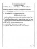
valid for serial numbers:
before 20850, Service Bulletin (SB) 5A-2:
Driving the output stage level tp a maximum witout a load...
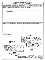
before 22600, SB 5A-3A:
Mounting the output trans reversed...
before 21176, SB 5A-1:
Second fan running slow...
as needed, SB 5A-4:
Truly balanced input stage...
That's all I have...
All other info is welcomr to this way...
(even for the PM-1200 or other Carvers)
CHeers,
Tarzan
I have the schematic of the 1.5 with some service notes.
valid for serial numbers:
before 20850, Service Bulletin (SB) 5A-2:
Driving the output stage level tp a maximum witout a load...
before 22600, SB 5A-3A:
Mounting the output trans reversed...
before 21176, SB 5A-1:
Second fan running slow...
as needed, SB 5A-4:
Truly balanced input stage...
That's all I have...
All other info is welcomr to this way...
(even for the PM-1200 or other Carvers)
CHeers,
Tarzan
Hi pjaneiro,
There are no changes for that listed for the PM 1.5 or 1.5a. The M-4.0t has a mod for turn of thump. The TFM 45 has a mod for turn off squeel. It may be in the back of the manual, I don't seem to have it.
Before you do anything. Does your unit have two blue dual section caps on the power supply board, or a circuit board with four capacitors on it near the middle, bottom (where the bottom bends up and straightens out again)? If it has the two blue caps, you need to replace that with the mod board. Some guys have installed the four caps without a board. These will cause all kinds of trouble.
-Chris
I have modded the amp with the new 4 caps, actually replaced them with higher voltages and capacitance values, just to be on the safe side, this unit is actually driving 4 15" subs at a rated power of 400w, when this baby goes on my chest want to implode and the party goers go crazy !!!!
but that damn squeel at power off drives me nuts, and that left channel noise also, i got m hands on part 2 of the service bulletin for the carver input board, that carver company liked to keep their secrets, once again, no info on wich jumper is wich...., i could take a guess and just cut the ones on the left channel but hey, i dont feel like turning on the amp and getting a nice 600w humm blowing the speakers away, 😉
i can take pics of the input board if any of you gents feel it might be needed
Hi pjaneiro,
Let's look at the TFM-45 shematic and figure out if the mod is backwards compatible. Could be the added capacitance is the problem by keeping the amp running longer.
-Chris
Let's look at the TFM-45 shematic and figure out if the mod is backwards compatible. Could be the added capacitance is the problem by keeping the amp running longer.
-Chris
Hi pjaneiro,
This mod addresses your problem directly as it applies to the TFM-45. It's meant to discharge the supply more quickly, so you may have caused this by increasing your capacitor size.
I would replace those with the proper value as this mod will directly heat the capacitor terminals. You don't want to do that.
-Chris
Attachments
Hi pjaneiro,
a couple of ideas from me:
1. The squeal is definitely coming from the OP-amps on the input ckt. Bob Carver said in an interview that he always adds pull-up resistors from op-amp outputs to LV(+) to force them into SE class-A operation, which should also fix the squeal issue - check whether they are there. If not, 10mA should do the trick.
If that does not solve the problem:
2. Why don't you run the audio signal output from the input pcb to the main amps inputs through a 5V reed-relay, fed by the LV via a resistor and a (sufficient) cap in parallel to the relay coil? This way the relay will switch on/off only after the LV is high enough, leaving some time for the OP-amps to settle, and will switch off before they die into a squeal.
Best,
- Status
- Not open for further replies.
- Home
- Amplifiers
- Solid State
- Carver PM-1.5 output noise and screech