Hello all,
I have a 1.5t that I used for a few years, before the protection circuit kicked in last year. I've just gotten around to taking a look, and I can see that the R60 and R58 resistors (both 2W) just after the +/- 125V rectifier outputs are both burned up. I've checked a few of the surrounding parts, but haven't seen anything obvious to cause these to burn up. Any ideas of what could have caused this? Any help would be greatly appreciated. Thanks!
I have a 1.5t that I used for a few years, before the protection circuit kicked in last year. I've just gotten around to taking a look, and I can see that the R60 and R58 resistors (both 2W) just after the +/- 125V rectifier outputs are both burned up. I've checked a few of the surrounding parts, but haven't seen anything obvious to cause these to burn up. Any ideas of what could have caused this? Any help would be greatly appreciated. Thanks!
Attachments
Not familiar with Carver gear, any service manual available?
How is R68 (15ohms), think is that something is shorting on the -12V rail downstream
but that would probably take out R68. Have you made any further checks on the protection issue like checking output & driver transistors, emitter resistors, generally any heat stressed items. You should build a dim bulb tester for first power up after parts replacement...
Have you checked for any obvious shorts on that -12V rail?
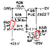
TBH those resistors are very marginally rated to begin with. R58 regularly dissipates 1.88 W, for R60 it's 1.58 W. Like most any sane person, I would go for 2x 2 W for the former and 3 W for the latter. 435 mW on 1/2 W rated R28 is hardly luxurious either, a 1 watter would be good there.
What is R58 even good for? And why are they using a 10 A transistor to provide what seems little over 20 mA - or is -50V5 a separate power rail (but then, what is the purpose of R60)?
Where did you find a schematic for this particular model anyway? HFE doesn't have the 1.5t, not to mention it claims I've exceeded my daily download quota since yesterday. Gah.
Thanks all for the help!
I've attached the service manual, hopefully they helps you all. I'll take a look at the items you've pointed out so far, but I haven't seen anything obvious. Running the hand-calc - I agree, those wattages do seem low, though I suppose this amp ran for almost 30 years trouble-free. Still, I'll be sure to uprate any replacements I get. I'll get back to you all if I find anything, thanks again.
I've attached the service manual, hopefully they helps you all. I'll take a look at the items you've pointed out so far, but I haven't seen anything obvious. Running the hand-calc - I agree, those wattages do seem low, though I suppose this amp ran for almost 30 years trouble-free. Still, I'll be sure to uprate any replacements I get. I'll get back to you all if I find anything, thanks again.
Attachments
I think Carver have the worst manual schematics I've ever seen.
Yes, it's nice their available, but you go blind then bonkers trying
to read the splotched scans 🙁
Though some folks have come through with nice schematics and layouts.
Also, I think this is one of those amps you need to be careful poking around
in there. If you've got to use a variac for testing, doesn't this have triacs that
kick in for ultra high current? And the commutator pairs?
Bummer for testing as my variac is only a 140V 10A variac, Variac.
The equipment says 22A Wow, that is a biggie.
Good luck and be careful.
Cheers,
Hello all,
A long-awaited update, but I replaced all of the obviously damaged components, and all the electrolytics, and I'm now troubleshooting a new problem. Upon power up, there is a ticking or clicking type noise, and the panel fault LED rapidly blinks. I understand this is typical of the protection circuit. Unfortunately I can't follow the manual troubleshooting exactly as I don't own a variac or a scope, though maybe I will have to buy those to do it. Anyone with experience have any pointers for trouble areas I should investigate first? Thanks
A long-awaited update, but I replaced all of the obviously damaged components, and all the electrolytics, and I'm now troubleshooting a new problem. Upon power up, there is a ticking or clicking type noise, and the panel fault LED rapidly blinks. I understand this is typical of the protection circuit. Unfortunately I can't follow the manual troubleshooting exactly as I don't own a variac or a scope, though maybe I will have to buy those to do it. Anyone with experience have any pointers for trouble areas I should investigate first? Thanks
Hello all,
A long-awaited update, but I replaced all of the obviously damaged components, and all the electrolytics, and I'm now troubleshooting a new problem. Upon power up, there is a ticking or clicking type noise, and the panel fault LED rapidly blinks. I understand this is typical of the protection circuit. Unfortunately I can't follow the manual troubleshooting exactly as I don't own a variac or a scope, though maybe I will have to buy those to do it. Anyone with experience have any pointers for trouble areas I should investigate first? Thanks
There are generally only a few things that will put an amp into protection... bad power supply, DC offsets on the outputs, oscillation or bad AC.
If you have a multimeter... Check all the voltage rails be sure they are near the right voltages and stable. Check DC offsets on the outputs and be sure they are stable. Check that nothing is getting really hot. Also check DC bias and offset adjustments for the outputs.
If your meter can check AC while ignoring DC check for high levels of AC on the outputs. Check the supplies for ripple in excess of a couple of volts. Check that the AC coming in is correct and stable.
Also double check your own work. Electrolytics are polarized and it's pretty easy to get one in backward. Check your solder for cold joints or bridges. Check any wires or plugs you had disconnected... and so on.
I had a look at the schematic you posted. Trying to read that would make my head explode. I hope you have or can find a better copy.
I do have a meter, unfortunately the amplifier isn't stable enough to be able to measure any of the rails - it trips nearly instantaneously. I'm positive the capacitor connections are correct, I double-checked them against both photos and the schematic (I agree that the scan is awful). The more I think about it, the more I think I'll have to invest in a Variac. The manual provides a method to bypass the triac on the regulator card and bring it up to about 30% power to check the voltage rails and shutdown circuits. I'm thinking that may be the only way forward, at this point.
- Home
- Amplifiers
- Solid State
- Carver m1.5t burned resistors