Hello
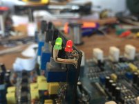
I have in the table, a Carpower 4/600 amplifier which, when turned on, the power light (green) and immediately afterwards the protection light (red), both at the same time.
I disconnected all IGBT (MAP6808) and IC (DRV6807) transistors but still with the same fault (power light and protection light at same time)
When I disconnect the rectifier diodes, delivered in source output +41 volts and -41 volts stable. power light (green) is lit as you would in normal operation
can anybody help me?
Greetings and thanks
Sorry, he did not understand me. Removing the rectifiers, the green power light goes on smoothly. I have even taken waveforms at the gate of MOSFET transistors of the power supply and is purely square.
When put the rectifiers, the power light green is turned and protective light red both at the same time, measure for 2 seconds is +41v and -41v, and then falls to 0v.
Greetings
When put the rectifiers, the power light green is turned and protective light red both at the same time, measure for 2 seconds is +41v and -41v, and then falls to 0v.
Greetings
Do you see a pulse of DC on any of the channels? If it's bridgeable, be sure to check on the bridging terminals of each channel.
You'll have to monitor the channels at the moment that the amp is powered up.
You'll have to monitor the channels at the moment that the amp is powered up.
Hello.
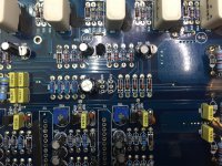
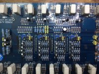
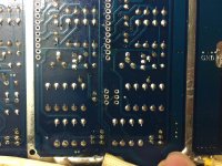
I leave a video and some pictures to have no doubt of what happens.
https://www.youtube.com/watch?v=RBPvW3eZrkA&feature=youtu.be
Greetings.
I leave a video and some pictures to have no doubt of what happens.
https://www.youtube.com/watch?v=RBPvW3eZrkA&feature=youtu.be
Greetings.
Attachments
I don't watch videos.
What I need requires that you measure the voltage with either a multimeter or an oscilloscope.
What I need requires that you measure the voltage with either a multimeter or an oscilloscope.
Hi guys
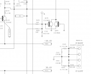
Reviewing all, by chance, I removed the Q26 and Q24 transistors, turned off the protection light and power supply works normally. But retired transistors are 2N5401 two units, which are tested and work perfectly. What role will these transistors?
regards
Reviewing all, by chance, I removed the Q26 and Q24 transistors, turned off the protection light and power supply works normally. But retired transistors are 2N5401 two units, which are tested and work perfectly. What role will these transistors?
regards
Attachments
Hello
Yes, it seems DC offset protection, it is a fault I've never had to repair. How I can solve?
Greetings.
Yes, it seems DC offset protection, it is a fault I've never had to repair. How I can solve?
Greetings.
Power up the amp and measure the DC voltage directly across the speaker terminals for each individual channel. Are any above ~0.050v DC?
Was it going into protect mode with those transistors in but the output transistors out of the circuit?
Yes, with IGBT transistors out of the circuit is entering protection. It has been removed Q26 and Q24 and remove protection light.
Measure the voltage across the speaker terminals with the output transistors out of the circuit.
Hi
These are averages I get in the speaker terminals:
CH1: -3.16VDC
CH2: + 3.15VDC
CH3: -3.12VDC
CH4: +3.13VDC
Greetings.
These are averages I get in the speaker terminals:
CH1: -3.16VDC
CH2: + 3.15VDC
CH3: -3.12VDC
CH4: +3.13VDC
Greetings.
Were the probes directly on the positive and negative speaker terminals for all of those readings?
If so, does the amp draw excessive current if you connect a jumper wire across the speaker terminals for any of the channels (no outputs in the circuit)?
If so, does the amp draw excessive current if you connect a jumper wire across the speaker terminals for any of the channels (no outputs in the circuit)?
Hello
Sorry, I made a mistake putting multimeter probes.
Really is:
CH1: + 3.16VDC
CH2: + 3.15VDC
CH3: + 3.12VDC
CH4: + 3.13VDC
Greetings.
Sorry, I made a mistake putting multimeter probes.
Really is:
CH1: + 3.16VDC
CH2: + 3.15VDC
CH3: + 3.12VDC
CH4: + 3.13VDC
Greetings.
I connected a jumper wire across the speaker terminals (+ and -) of any channel, i get 0.001v . If I connect a speaker of 4 ohms, I get 0.004v.
Do what you did in #19 again but reinstall the two DC offset transistors first.
Does connecting the jumper across any single channel allow the amp to power up without going into protect mode?
Does connecting the jumper across any single channel allow the amp to power up without going into protect mode?
- Status
- Not open for further replies.
- Home
- General Interest
- Car Audio
- Carpower 4/600 IGBT. lights power and protection same time