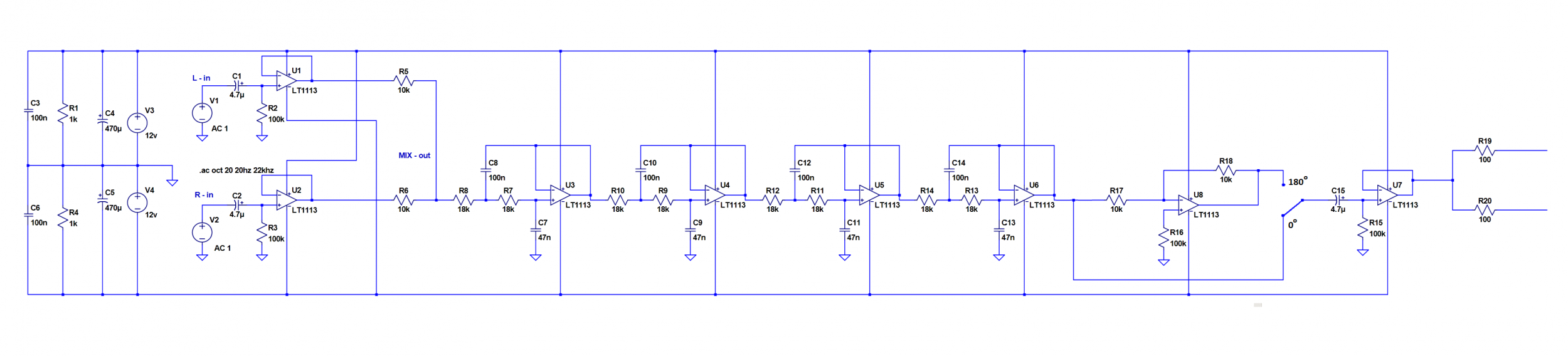
Hi could anyone please comment on the following circuit. Its an car subwoofer LP filter... tkx
http://files.diyaudio.com/forums/gallery/data/1785/sch.png
An externally hosted image should be here but it was not working when we last tested it.
http://files.diyaudio.com/forums/gallery/data/1785/sch.png
Last edited:

Car LP Filter.... Version 2
any feedback wold be great ... tkx 😀
An externally hosted image should be here but it was not working when we last tested it.
any feedback wold be great ... tkx 😀
An externally hosted image should be here but it was not working when we last tested it.
First: I’m unsure you are really need in doubled buffer for output.
Second. There will be strong crosstalk in input cable because of the link between input capacitors.
Third: There’s no necessity to duplicate op-amps for direct and reversed signals.
It would be better to use one amp for mixer and next amp as inverter.
To switch phase it is enough to connect the filter input before or after inverter.
Fourth:
It is good practice, to minimize THD and to get maximal noise rejection ,to have direct and inverted inputs loaded by symmetrical current.
So, some of grounded inputs should contain resistors and some of resistors should be corrected.
For example:U7. The equivalent resistance at inverting input is paralleled R17||R18 -5kOhm, then to provide doubled current for U7 and U8 the R15 and R16 must be 5 kOhm too.
thx for the feedback
R15 & R16 ar a simulation of a 100K potentiometer because I couldn't find it in LTSpice... as for the input could you give me ani suggestion
is this better?

😀
R15 & R16 ar a simulation of a 100K potentiometer because I couldn't find it in LTSpice... as for the input could you give me ani suggestion
is this better?
😀
OK, thanks for explaining.its just for simulating in LTSpice ... R1 and R4 are dummy-loads
I'm a beginner myself, hopefully somebody more experienced can share his/her view.
I’d put it in this way.
Separated inputs will allow to take signal due Y-splitter in parallel with amp for component speakers. Though, there always is risk to catch the ground loop noise when connecting two inputs with different ground topology.
I thought about op275 with FET differential , LT1313 should fit too.

Separated inputs will allow to take signal due Y-splitter in parallel with amp for component speakers. Though, there always is risk to catch the ground loop noise when connecting two inputs with different ground topology.
I thought about op275 with FET differential , LT1313 should fit too.
It doesn’t like, but by LT1113 datasheet’s recommendation there is possibility you will need in parallel capacitors 27pF with R5,R6 and R13 resistors
OP275 works without them , it was checked by practice.
For OP275 , if you plan to use it with signal higher than 4V RMS it would be better to put 10k resistor in series with input capacitors. First order high pass C1R7 and C2R8 goes off ,but it is better than clipping.
OP275 works without them , it was checked by practice.
For OP275 , if you plan to use it with signal higher than 4V RMS it would be better to put 10k resistor in series with input capacitors. First order high pass C1R7 and C2R8 goes off ,but it is better than clipping.
http://www.diyaudio.com/forums/gallery/showfull.php?photo=7933
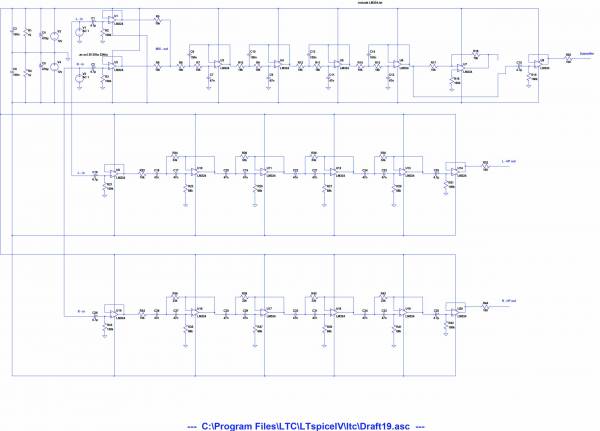
this is the final version... pls give feedback so I can start building it... tkx
http://www.diyaudio.com/forums/gallery/showfull.php?photo=7934
Last edited:
It should work.
Those lm324 they are good for sub, but I don’t know how they are for music.
I suspect they are a bit noisy and possible not very quick for modern standards.
Those lm324 they are good for sub, but I don’t know how they are for music.
I suspect they are a bit noisy and possible not very quick for modern standards.
These were widely used in car amps they are good to use.
Take a look on “eserviceinfo.com” manuals for car amps it will give you idea how they are designed.
You can copy their isolation buffer how it is. In my opinion, most successful but most complex buffers have Alpine amps.
In addition to your schematics.
For safety of your signal source it would be better to put 2kOhm resistors on positive inputs of U1, U2, U9, U15.
To be more precise, R5||R6 is part of R8 resistance for filter. Take 12k for all of them(R5 R6 R8), it will give you total 18k.
- Status
- Not open for further replies.
- Home
- Loudspeakers
- Subwoofers
- car subwoofer filter 48 db/octave