I am designing a car smps that will draw at least 100A peak through the transformer, using push-pull topology. I am going to use lossless snubbers (diode-cap-ind combo) for this one, and I made some quick calculations regarding leakage inductance losses just for the fun of it.
I used the formula for energy stored in an inductor, E_L=0.5*L*I^2 and assumed a leakage inductance of 2uH (3 turns primary ETD34 core). I switch at a frequency of 55kHz (110e3 switchings per seconds) which would give the power fed into the leakage inductance = 110e3*0.5*2e-6*100^2 = 1100W. I dont have much experience in smps design, and therefore I wonder - is this really correct? Would I really lose this much power if I were to use RC-snubbers instead of trying to regain the energy?
I used the formula for energy stored in an inductor, E_L=0.5*L*I^2 and assumed a leakage inductance of 2uH (3 turns primary ETD34 core). I switch at a frequency of 55kHz (110e3 switchings per seconds) which would give the power fed into the leakage inductance = 110e3*0.5*2e-6*100^2 = 1100W. I dont have much experience in smps design, and therefore I wonder - is this really correct? Would I really lose this much power if I were to use RC-snubbers instead of trying to regain the energy?
Say the loss is 200W then (100W per primary of the push-pull windings), and at 110kHz per primary I have 9us at 50% duty for the snubber inductor to leave all energy to the power rail, that means 100W must flow into the rail at 50% duty cycle leaving me with an average current of 2*100/10 = 20A flowing through the diodes with a peak value of some hundreds of amps. I guess this implies that the dioded used must be able to handle 20A average current, and will dissipate an average of at least (the shape of the current affects the rms value) 20*0.6 = 12W each? Which means that my snubber which has 4 diodes in total dissipates 4*12 = 48W minimum at 100A primary current?
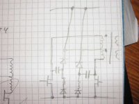
Will the snubber scheme in the attached picture work, or will I need to use the scheme in
http://powerelectronics.com/images/509PET22.pdf?
The currents involved together with a capacitor requirement in the area of 50uF+ scare me, are there capacitors in that size that handle 25Arms (according to equations in the paper) and dont cost very much?
Eva, how would you construct the clamping for this smps?
Attachments
Do you understand that most of the clamping is achieved by optimizing mutual coupling between both push-pull primaries and with the help of the own body diodes?
Also, do you understand that MOSFETs rated at 60V Vds allow some useful time to the primary to primary leakage inductance to be energized before Vds reaches the avalanche thresold at turn off?
You may have to build a prototype and check it yourself, but if things are done properly, plain RCD or RC snubbers may do the job with reasonable dissipation.
I have wound a transformer for leakage inductance measurements now, ETD34-3F3, 3+3:16+16 with 7x0.7mm strands for primaries and 2x0.6mm strands for secondaries. I shorted both outputs to the center tapped ground, and I left the primary center tap open. I placed a 22nF capacitor between both ends of the push-pull primaries, and measured the self resonance frequency to ~3.9 MHz yielding a total leakage inductance of 75 nH for both primaries in series. If this is the way to do it, then I guss the leakage inductance for each primary is 37.5 nH, as each primary drives both secondaries simultaneously (center tapped, full bridge transformer feeding inds/caps).
At 55kHz (110kHz) switching frequency and 100A, this translates to ~20W total being lost through the leakage inductance if I choose to clamp it all away.
Before anyone points it out, this smps is designed to withstand ~150-200W continiously from 10-16V, with the capability of short excursions up to full power at above 600W@10V battery voltage.
You should short one of the primaries (and also the secondaries) and measure the leakage inductance as seen from the other primary. This will reflect more or less the actual working conditions, since all windings will provide clamping of the inductive turn-off spike in some way.
I redid it with one primary shorted, resulting f_o=4.45MHz with 22nF resulting in 58nH for one primary. Is this a good or bad value considering this application?
It seems low enough, however, you can try to further reduce it by playing around with winding layout. Hint: try to improve coupling between both primaries, bifilar winding may do the trick. Also try to place the primaries sandwitched between the two secondaries.
Eva said:It seems low enough, however, you can try to further reduce it by playing around with winding layout. Hint: try to improve coupling between both primaries, bifilar winding may do the trick. Also try to place the primaries sandwitched between the two secondaries.
The windings are in the order: s1, p1, p2, s2. The first secondary did fit one layer, so did each of the primaries, but the second secondary ended up using more than one layer since there were so much copper entering and exiting the coil former. Here is a picture of the thing -> http://wintermute.csbnet.se/~zilog/PICT0181.JPG and here is another http://wintermute.csbnet.se/~zilog/PICT0184.JPG
- Status
- Not open for further replies.
- Home
- Amplifiers
- Power Supplies
- car smps snubbers