@Tubelab_com
Amazing! What's the 4 tube amp?
By the way, what's the guitar that can be seen in the first picture?
Looks nice.
Amazing! What's the 4 tube amp?
By the way, what's the guitar that can be seen in the first picture?
Looks nice.
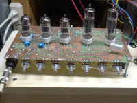
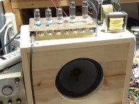
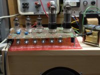
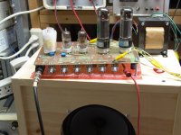
The 4 tube amp is seen in the guitar picture sitting on top of the black speaker cabinet. Its schematic was included, and here are a few more pictures. It evolved from Amp 1.4 discussed in the long Hundred Buck Amp Challenge. It could still be built for less than $100 today.
The guitar is a no name Chinese guitar I got on Ebay for about $40. I also got a Chinese Strat clone at the same time, also for about $40. A week or two later the same seller had some Chinese clones of a Fender bass, so I got one of those too. Both guitars are easier to play and have better tone than the Indonesian Fender Squire Strat that I sold to pay for all three.
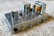
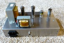
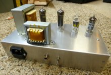
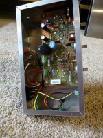
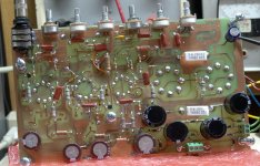
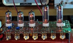
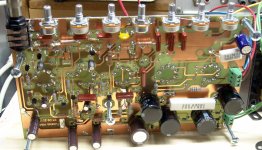
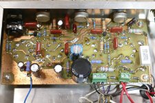
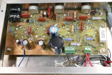
The larger amp with 5 tubes is one of two nearly identical amps I made for the HBAC. Both were based on the "Marshall 18 Watt" schematic found floating around the web. One used 9 pin tubes (UL84's and UCC85's) and the other used octal output tubes (50JY6's). Both ran series string heater setups for use with tubes that were very cheap at the time. The octal version did see some use with 12AX7's, EL34's and a real guitar amp OPT. I added several experiments using mosfets for dynamic gain control which failed and were removed from the PC board. I also used cheap TV tubes for the gain stages. They had less gain than a typical 12AX7, so I added an extra tube. This turned out to have WAY too much gain. So much that the amp was impossible to tame, so that two gain stages were bypassed. The 9 pin schematic is enclosed, but much of the solid state stuff was bypassed during early testing. Some pictures are included. The foam wrapper around the input tube helped tame microphonics seen at high gains.
The guitar is a no name Chinese guitar I got on Ebay for about $40. I also got a Chinese Strat clone at the same time, also for about $40. A week or two later the same seller had some Chinese clones of a Fender bass, so I got one of those too. Both guitars are easier to play and have better tone than the Indonesian Fender Squire Strat that I sold to pay for all three.
The larger amp with 5 tubes is one of two nearly identical amps I made for the HBAC. Both were based on the "Marshall 18 Watt" schematic found floating around the web. One used 9 pin tubes (UL84's and UCC85's) and the other used octal output tubes (50JY6's). Both ran series string heater setups for use with tubes that were very cheap at the time. The octal version did see some use with 12AX7's, EL34's and a real guitar amp OPT. I added several experiments using mosfets for dynamic gain control which failed and were removed from the PC board. I also used cheap TV tubes for the gain stages. They had less gain than a typical 12AX7, so I added an extra tube. This turned out to have WAY too much gain. So much that the amp was impossible to tame, so that two gain stages were bypassed. The 9 pin schematic is enclosed, but much of the solid state stuff was bypassed during early testing. Some pictures are included. The foam wrapper around the input tube helped tame microphonics seen at high gains.
Attachments
-
 Chassis_1.jpg566.1 KB · Views: 56
 -
 Chassis_2.jpg494.1 KB · Views: 57
 -
 Chassis_3.jpg467.7 KB · Views: 53
 -
 Chassis_4.jpg542.2 KB · Views: 55
 -
HBAC_5T.pdf29.1 KB · Views: 64
-
 BoardTop.jpg439 KB · Views: 69
 -
 DSC00807.JPG446.6 KB · Views: 49
 -
 DSC00812.JPG432.5 KB · Views: 59
 -
 DSC00818.JPG431.2 KB · Views: 54
 -
 ES_bottom.jpg528.3 KB · Views: 65
 -
 NoGlow.jpg559.2 KB · Views: 57
 -
 UnderTheDeck.jpg419.7 KB · Views: 72

I have a version of the JCM800 made with subminiature tubes in the pipeline, but still have to send the PCB for fabrication.
It will use 6N17B in the first two stages,the 6N16B for the buffer an phase splitter and a class AB power amp made with 2 6P30B-R.
Let's see how loud this will be.😀
It will use 6N17B in the first two stages,the 6N16B for the buffer an phase splitter and a class AB power amp made with 2 6P30B-R.
Let's see how loud this will be.😀
Hi
I have a recording of the amp attached. The amp is a bit quiet but works. I have played next to it, so you can notice the difference of volume between my strumming and the sound of the amp.
I think if I use 2 valves in PP, it will be ok.
Please be warned that my playing is baaadddd and, when recording, I get nervous, so I do many mistakes. Anyway, please give a listen and tell me what you think of the amp.
Cheers,
Pedro
Attachments
Hi George,The 4 tube amp is seen in the guitar picture sitting on top of the black speaker cabinet. Its schematic was included
Your Amp 1.5 looks quite interesting to me and I have read The hundred buck-amp challenge trying
to find the value of R12 and R15 without much luck. I got lots of radio tubes to play with!
I would be guessing R12 is 500k and R15 is 250k. An I close?
Since I can't remember exactly what I did, I picked up the amp and poked around inside it with a DVM. All three pots are 1 Meg. I assume that you are going by this schematic, since it is the one that matches the amp in hand. There were several iterations of that amp and many were posted in the HBAC thread.
Attachments
Yea, I have been sorting through them all trying to figure out the changes over time.There were several iterations of that amp and many were posted in the HBAC thread.
Thank` for all the hard work and knowledge by the way!
The one I have been studying is GTA_4T_11-4. It has One extra diode (D6) and a 5 watt R25.
Looks like no R32 after D5 like shown in your latest post of GTA_4T_11-10.
There is a lot to try to take in and sort out. I`m sure all would work but i`m trying for the latest.
The extra diode is redundant once the connection that feeds the B+ to the amp got moved to the other side of D3 and D4. R32 was initially there to create sag by mimicking internal resistance of a rectifier tube. Once I moved the preamp circuitry to the screen grid side of R30 the amp mimics a saging rectifier tube quite well without R32. The early versions of this amp had a 2 watt resistor for R25 and I managed to blow one. The amp I use has a 3 watt carbon film resistor and it has lived for years. R31 is now 240 ohms 5 watts in my current amp, but our line voltage runs high, often about 125 volts.
There might be a few other things I changed, but don't remember.
The amp has always had the high gain pentode stage first, and the medium gain triode stage second. Pentodes are inherently more microphonic than triodes since there are more grids to rattle when the DUMM BLONDE puts the amp on top of the speaker cabinet and dimes all the controls. Several forum members suggested swapping the two stages to help this, but I never got around to trying it.
These may help:
Attachments
Thank you for the detailed reply and all the extra information!
Yea, our line voltage is also high. About 127v for us.
Makes you have to figure out how to get rid of some voltage a lot of the time!
Yea, our line voltage is also high. About 127v for us.
Makes you have to figure out how to get rid of some voltage a lot of the time!
Hi guys,
I would like just to give an update on my experience with the 12DY8 as an amplifier.
The sound at 12V is good but very low in volume. However, I have increased the voltage to 50V and the difference in volume is huge. I am using the triode as the pre-amp and the tetrode connected to a 4kΩ transformer and it works very well.
I think, now, I have a one-tube amp that is low voltage for bedroom use and pretty cheap too.
Cheers,
Pedro
Is the goal low voltage or miniature tubes?
Here is a low voltage solution, but using a PL504 ...
LV amp PL504
... and came across this article you have probably already seen Tubes with low plate voltages
Here is a low voltage solution, but using a PL504 ...
LV amp PL504
... and came across this article you have probably already seen Tubes with low plate voltages
Hi
Thanks for the links.
I wanted to do a 1 valve low voltage amp.
The 6N16B also works well at low voltage, but I wanted to try these valves made for car audio.
The tetrode on the 12DY8 is capable of much more current drive comparing to the 6N16B, so I thought that I could take advantage of this valve having high current at low voltage.
Cheers
Pedro
- Home
- Amplifiers
- Tubes / Valves
- Car radio valves 12AL8, 12DY8 max power