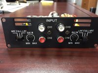
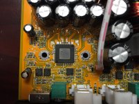
This is a tear-down of a car amplifier from Stetsom. It used TAS5630 as the amp chip. I can see there are total 6 no. of 4558 opamp at the input. I guess they are used for LPF, HPF, band pass and volume adjustment.
From the spec it says HPF cut off: 90 Hz and LPF cut off 90Hz.
I would like to know if the filter stage used single supply or dual supply? Does anyone have the circuit diagram of the input filter used here ?
Appreciate your thoughts ..
From the spec it says HPF cut off: 90 Hz and LPF cut off 90Hz.
I would like to know if the filter stage used single supply or dual supply? Does anyone have the circuit diagram of the input filter used here ?
Appreciate your thoughts ..
Attachments
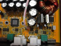
Looks like single-supply as there isnt any decoupling of the negative rails.
Thanks doctormod, I also guess that.
Can you guess the type of filter they used or if you have schematic? There are 12 opamps (6 no. 4558) for 4 SE channel. i.e. each channel is using 3 op-amps.
From a schematic it would cleary be seen.
With 3 opamps i would guess 4th order Linkwitz-Riley-filters (24dB/octave) made from 2 Butterworth in series with an All-pass-filter at one output (HP or LP), or 2th order Linkwitz-Riley-filters (12dB/octave) made with Sallen-Key-topology and an inverter at one output for the 180° phase shift.
But only guessing.
Last edited:
From a schematic it would cleary be seen.
With 3 opamps i would guess 4th order Linkwitz-Riley-filters (24dB/octave) made from 2 Butterworth in series with an All-pass-filter at one output (HP or LP), or 2th order Linkwitz-Riley-filters (12dB/octave) made with Sallen-Key-topology and an inverter at one output for the 180° phase shift.
But only guessing.
Something like this ?
State variable filter - Wikipedia, the free encyclopedia
- Status
- Not open for further replies.
- Home
- Amplifiers
- Class D
- Car Amplifier Filter using 4558