In some diy builds I see caps near each output device. This is mostly done by Panasonic FC caps bypassed with WIMA MKP. I assume they are placed between the rails and ground.
Makes this sence for class A or is it for what it's worth? And is this worth the extra complexibility of the pcb (neglecting the extra costs of the parts)?
Makes this sence for class A or is it for what it's worth? And is this worth the extra complexibility of the pcb (neglecting the extra costs of the parts)?
Attachments
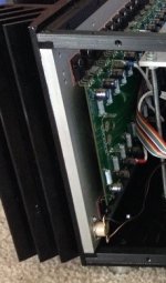
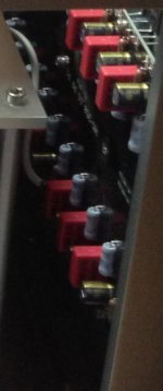
> caps near each output device
My parents used to go dancing in a converted chicken coop. When the joint was jumping, the floor bounced a lot.
In principle, we could put a rock under the joist at each dancer and absorb the jolt locally instead of through long floor joists.
I've actually done this, in a kitchen converted from a dairy shed. As said, it is hard to get a major improvement with rocks of manageable size. For the price of rocks (or P-sonic caps), it isn't a real waste of money. (I'm now doing the same in another old shack, but pouring massive footings, like a 5000u cap at every 3rd transistor.) And a fat PCB trace is a lot "stiffer" than a 6x6 beam.
I used to go dancing in a converted chicken coop back in the 60's. But it was near Montreal - not in Maine. Played gigs there too. Good memories.
Thank you all. I have decided to go for it.
Now adjust the pcb design and find some caps that will fit.
Now adjust the pcb design and find some caps that will fit.
Caps near output device
Many years before I have read that these caps should help to compensate inductive component of supply wiring, therefore improving stability.
Some guys consider them as speed up-caps or as a quality improvement for usually big sized smoothing caps.
Many years before I have read that these caps should help to compensate inductive component of supply wiring, therefore improving stability.
Some guys consider them as speed up-caps or as a quality improvement for usually big sized smoothing caps.
This is common practice with class AB amps, why should it be any different for class A?
There is very high continuos ripple current in class A amplifier.
There is also high countinuos ambient temperature.
Cap diameter is small.
Nominal ripple current is small.
I think they will not last long,....
There is very high continuos ripple current in class A amplifier. There is also high countinuos ambient temperature.
Cap diameter is small. Nominal ripple current is small. I think they will not last long,....
The ripple current is unlikely to be shared equally, so some capacitors will fail prematurely.
Use 105C capacitors, with overrated ripple current and good ventilation.
Last edited:
- Status
- Not open for further replies.
- Home
- Amplifiers
- Pass Labs
- Caps near each output device