Hello! Hope someone could help me out, and hopefully I can explain myself clearly enough my English is not so good.
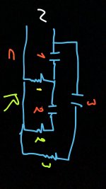
I'm wondering how would capasitors behave on high pass filter where is three speakers and three capasitors and all capasitors are for high pass use. I draw a 'pretty' picture about the circuit. R1, 2 and 3 are the speakers.
I would need a filter where C1 cuts off freqs under 80hz, C2 and C3 cut off freqs under 4000hz. C2 cut off freq is not so important..let's say somewhere between 2-6khz
Attachments
I'll try to start the ball rolling.
We would need a clearer description of your intentions. Include details of the speaker drivers R1, R2 and R3, their nominal impedance figures, and decide the exact filter frequency you wish to apply to each - not a vague requirement like "let's say somewhere between 2 - 6 kHz".
I'm a bit confused. Would you settle for both R2 and R3 filtering at 4,000 Hz? Are both R2 and R3 similar high frequency drivers? I presume R1 is a midrange driver?
Last edited:
I'm wondering if mika is asking how the combination of C1 and C2 would behave in his circuit.
i.e. Would driver R2 'see' the combined capacitance of C1 and C2?
i.e. Would driver R2 'see' the combined capacitance of C1 and C2?
Kinda sorta, C1 and C2 are in series, but then there's the R1 to ground to account for.
More like a second order filter for driver 2. The math gets messy fast though.
Not sure whether I've seen a crossover with this topology.
More like a second order filter for driver 2. The math gets messy fast though.
Not sure whether I've seen a crossover with this topology.
I thought it wouldn't be as simple as a straight series combination, thanks for explaining that.
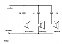
Your attachment certainly looks like the way to go.
Your attachment certainly looks like the way to go.
Not a speaker guy, but even I can see this isn't such a good idea.
The electrical behavior of driver 1 will affect the voltage at driver 2.
Driver 1 is not a resistor, so it seems like that would be bad.
Now, just two drivers connected in series can work ok, because the
symmetry means the input voltage will divide equally between them
(except for the LF resonances which will vary a bit, see Bose 901 or the Sweet Sixteen).
Last edited:
Sorry Mika but that is a terrible crossover design.
Please tell us more about which exact speakers we are talking about, specially each one´s impedance, and desired crossover frequencies.
We will probably suggest a much more reasonable crossover.
What Country are you in?
It will strongly influence parts suggestions, were to buy crossover components, etc.
- Home
- Design & Build
- Construction Tips
- Capasitor behavior on crossover