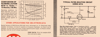
I took a look at that CBS 6216 "Filter-Reactor" and happily (?) found one of those tubes in one of my junk boxes.
The the CBS schematic has the screen grid connected to the positive rail, and the tube regulates the negative.
It is not a classic capacitance multiplier, it uses negative feedback to buck out the ripple. Why in the negative rail? Well there are no "P" type tubes.
The CBS circuit shows a 150mV p-p ripple at 80mA, with 20uF on the output and 8uF on the input, 100mV better than 12H choke. Perhaps good in 1953. The tube circuit drops out like 550 Ohm resistor.
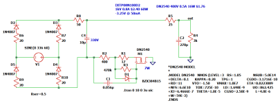
I reconstructed the the circuit using a depletion mode FET, the well known DN2540. Maybe a candidate for my constant current loaded D3a phono pre-amp?
With small-ish filter caps I got 60dB attenuation of the 120Hz, but as I have loads of 270uF caps, I inserted that into the sim and got better results, 120Hz attenuated like 90dB, or with this setup where I'm planning to use lower voltage for the CCS, I'm dropping out 130V by choice.
The advantage of using a N-channel depletion mode FET is that the case is the drain, which make insulation unwanted.
A beefier higher voltage IXTP08N100D2 could also be used, still low cost and in stock.
I saw some Dutch guys selling an electronic choke and got curious. They offer no schematic for this.
Perhaps a HV P-MOS would work? I used a highest voltage PMOS in the LTspice library, and got decent results.
Again I optimized the circuit with my needed voltage drop.
It behaves more like an inductor. Over-voltage on the FET can be handled with a TVS diode, I inserted a couple of Zeners.
As the whole thing floats on high voltage it needs voltage insulation, and with my 60mA load ~ 6W of heat needs go into the air via heat-sinking, or at least 3W for the FET. Like a choke, it is not connected, or referenced to ground. The resistors can be thru-hole ceramic.
As this power supply is not for a power amplifier I see no need to put the rectifier bridge negative to hard ground. Rectification deserves a its own chapter. Fast switching transients from rectifiers will excite any transformer leakage inductance, and this should be minimized and filtered with line filters. 120Hz mixed in with the sound signal has the potential to make intermodulation products in the audio range. It is easier to filter out higher frequencies, and their eventual intermodulation mixing products should be well outside the audible range. Magnetic fields from 60Hz iron is a problem, both for chokes, output/input and power transformers.
With two of those 270uF cap the 120Hz attenuation is like 120dB. Noise is in the micro volts range. Not too many HV P-MOS FETs out there to choose from.
It still would need a voltage regulator, as this proposition only gets rid of hum, but this should be simpler. It could very well be a shunt regulator.
The the CBS schematic has the screen grid connected to the positive rail, and the tube regulates the negative.
It is not a classic capacitance multiplier, it uses negative feedback to buck out the ripple. Why in the negative rail? Well there are no "P" type tubes.
The CBS circuit shows a 150mV p-p ripple at 80mA, with 20uF on the output and 8uF on the input, 100mV better than 12H choke. Perhaps good in 1953. The tube circuit drops out like 550 Ohm resistor.
I reconstructed the the circuit using a depletion mode FET, the well known DN2540. Maybe a candidate for my constant current loaded D3a phono pre-amp?
With small-ish filter caps I got 60dB attenuation of the 120Hz, but as I have loads of 270uF caps, I inserted that into the sim and got better results, 120Hz attenuated like 90dB, or with this setup where I'm planning to use lower voltage for the CCS, I'm dropping out 130V by choice.
The advantage of using a N-channel depletion mode FET is that the case is the drain, which make insulation unwanted.
A beefier higher voltage IXTP08N100D2 could also be used, still low cost and in stock.
I saw some Dutch guys selling an electronic choke and got curious. They offer no schematic for this.
Perhaps a HV P-MOS would work? I used a highest voltage PMOS in the LTspice library, and got decent results.
Again I optimized the circuit with my needed voltage drop.
It behaves more like an inductor. Over-voltage on the FET can be handled with a TVS diode, I inserted a couple of Zeners.
As the whole thing floats on high voltage it needs voltage insulation, and with my 60mA load ~ 6W of heat needs go into the air via heat-sinking, or at least 3W for the FET. Like a choke, it is not connected, or referenced to ground. The resistors can be thru-hole ceramic.
As this power supply is not for a power amplifier I see no need to put the rectifier bridge negative to hard ground. Rectification deserves a its own chapter. Fast switching transients from rectifiers will excite any transformer leakage inductance, and this should be minimized and filtered with line filters. 120Hz mixed in with the sound signal has the potential to make intermodulation products in the audio range. It is easier to filter out higher frequencies, and their eventual intermodulation mixing products should be well outside the audible range. Magnetic fields from 60Hz iron is a problem, both for chokes, output/input and power transformers.
With two of those 270uF cap the 120Hz attenuation is like 120dB. Noise is in the micro volts range. Not too many HV P-MOS FETs out there to choose from.
It still would need a voltage regulator, as this proposition only gets rid of hum, but this should be simpler. It could very well be a shunt regulator.