Two questions:
Please confirm my drawing in the picture I drew below.
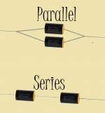
I do have series vs. parallel wiring diagrams correct, yes?
And please confirm my understanding of this (values randomly selected):
Please confirm my drawing in the picture I drew below.
I do have series vs. parallel wiring diagrams correct, yes?
And please confirm my understanding of this (values randomly selected):
- A pair of 240uF 100v wired in series = 240uF 200V.
- A pair of 240uF 100v wired in parallel = 480uF 100V.
Attachments
- A pair of 240uF 100v wired in series = 120uF 200V.
- A pair of 240uF 100v wired in parallel = 480uF 100V.
240uF + 240uF = 480uF
Last edited:
Electrolytic capacitors wired in series won't divide the voltage equally.
So allow a large safety margin.
So allow a large safety margin.
Electrolytic capacitor wired back to back to pass AC and block DC will block effectively in one direction and potentially leak badly in the other direction. Each electrolytic should be rated to block ALL of the worst case DC voltage plus half the worst case AC peak signal.
It is only reasonable to assume the leaking electrolytic has no blocking capability.
That is not "allow a large safety margin"
That is design for the voltages likely to be present when worst case occurs.
It is only reasonable to assume the leaking electrolytic has no blocking capability.
That is not "allow a large safety margin"
That is design for the voltages likely to be present when worst case occurs.
Electrolytic capacitor wired back to back to pass AC and block DC will block effectively in one direction and potentially leak badly in the other direction. Each electrolytic should be rated to block ALL of the worst case DC voltage plus half the worst case AC peak signal.
It is only reasonable to assume the leaking electrolytic has no blocking capability.
That is not "allow a large safety margin"
That is design for the voltages likely to be present when worst case occurs.
For safety, a resistor of the same value of a few kOhm across each cap was a scheme sometimes used in power supplies of tube amps.
That applies when you have a pair of capacitors biased in the same direction to resist a voltage that exceeds the rating of the capacitors.
These equalising resistors are mandatory for that duty.
These equalising resistors are mandatory for that duty.
"AndrewT' you are thinking about signal coupling capacitors, while I am thinking about vacuum tube high voltage DC power supplies.
Some people argue that equalising resistors are not needed, as the caps will adjust themselves according to their leakage behaviour. I am not convinced.AndrewT said:That applies when you have a pair of capacitors biased in the same direction to resist a voltage that exceeds the rating of the capacitors.
These equalising resistors are mandatory for that duty.
Roger Modjeski of Music Reference is one who thinks they are a bad idea, I've not heard of anyone else. I too am not convinced. I do like his RM9 amplifier though.
Craig
Craig
I am thinking about vacuum tube high voltage DC power supplies.
This is precisely in this application where I saw the voltages equalising resistors.
Some people argue that equalising resistors are not needed, as the caps will adjust themselves according to their leakage behaviour. I am not convinced.
One can't exclude the possibility of unequal leakages.
Unequal leakage is almost guaranteed. The result is that the total voltage will apportion itself across the two caps so that their leakage currents are equal. Provided that the two caps are similar (e.g. nominally identical) this should be good enough, as the one with the better oxide film will have more voltage across it. Equalising resistors will increase the voltage across the cap with the weaker oxide, by increasing the leakage current through it.
I would imagine that using this technique (no resistors) would require some headroom in voltage specs.
I would imagine that using this technique (no resistors) would require some headroom in voltage specs.
- Status
- Not open for further replies.
- Home
- Source & Line
- Analog Line Level
- Capacitors wired in Series vs. Parallel - Please verify my understanding