2. Sometimes I see "Accelerator" capacitor on the amplifier PCB, in the input of V+ to ground. Sometimes not.
Sometimes it is a few hundred uF ELKO or a couple of nF fouil cap.
A, Is this cap really necessary or not??
B, Should be ELKO or foil cap?
C, Is there any rule for calculating such a capacitor's value?
My interpretation of your 'in the input of V+' is 'where V+ joins the pcb'.
The answer is yes, it is normally a good idea to decouple at that point.
In general terms it reduces the effects of the characteristics of the V+ supply wiring to the pcb. Hence it encourages stability. Normally an electrolytic is used. (I think the value depends upon the application... maybe other guys can advise better than me).
3. This is an evergreen question 🙂
What kind of input cap is good?
In some cases I see ELKO in the input, but sometimes foil cap.
Which is better?
This is a very , very general guide...
Electrolytics are best for storage of power supply charge, high ripple currents, and relatively low frequency.
Film are best for passing a signal, low current, and relatively high frequency.
Therefore, for an input (i.e. in what people often call the 'direct signal path') then film type is preferable. They also have better tolerances and lower leakage.
Thanks Gordy!
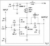
But what about something like this:
Yes, I also use the same.The two resistors of the voltage divider are effectively in parallel, and the 'new' capacitor shunts them to ground at AC signal level. Therefore the 'large value' resistor becomes the effective input impedance. As a FET gate takes almost no current the value of this 'large value' resistor can be high, typically 100k or more.
But what about something like this:
Attachments
De-coupling capacitance has one major function.
To attenuate supply rail voltage sag when current is demanded by the load.
It does this by holding a small charge ready for changes in current demand.
Very fast changes in current demand can be best met with a film capacitor. This capacitor must be placed very close to the device that adjusts the current output.
Cost and location demand a small component.
A second de-coupling cap installed to meet fast changes in current demand can be a high quality electrolytic. This too should be located fairly near the devices that adjust current output.
The smoothing caps in the PSU meet the slow changes and medium speed changes in the current demand. These can be located farther away since the inherent inductance in the connections (cables and traces) has less deleterious effect on meeting the slower changes in current demand.
Thanks!
I know it, but I just wanted to know the experience of people in this them.
Greets:
Tyimo
I know it, but I just wanted to know the experience of people in this them.
Greets:
Tyimo
AndrewT, I agree absolutely with what you have pointed out. I have also some listening impressions that I tried to correlate with caps quality and their location.
Pulse current demand is the most difficult thing for solving. Installing shunt film caps improves sound, but only partially. Even bigger polypropylene cap 30-50uF does not provide radical solution. PS electrolytics still contribute with a kind of “echo” effect, make sound a bit dark, and their action provides ground for those statements “ all correctly designed amps sound similar “. I almost agree with it, since 99,9% transistor amps based on the same PS philosophy.
Best answer to pulse current demand is provided by simple shunt PS, where the big electrolytics are cut away from the schematics by the current source contained in the shunt PS. But we understand, that shunt PS approach is not compatible with main AB stage idea – power efficiency.
These problems related with pulse current demand could be solved in rather simple and well known manner – use class A output stage like Zen (without current source modulation) or Follower. Special attention will be needed to output “cap” design. But it is the most simple way to escape from “transistor” sound limitations.
As for film shunts installed just on the PS electrolytics, their purpose has nothing to do with pulse current demand, they should suppress HF artefacts from switching diodes in PS rectification bridge.
Gordy!
What is the "ideal" input impedanece of a Mosfet Source follower?
Tyimo
What is the lowest input impedance, which not necessary to use that shunt capacitor?Therefore the 'large value' resistor becomes the effective input impedance. As a FET gate takes almost no current the value of this 'large value' resistor can be high, typically 100k or more.
What is the "ideal" input impedanece of a Mosfet Source follower?
Tyimo
Hi!
Nobody knows how to calculate the value of the shunt capacitor in the voltage divider???
I see many different values from 0.47 MKP to 2000uF ELKO😕
Nobody knows how to calculate the value of the shunt capacitor in the voltage divider???
I see many different values from 0.47 MKP to 2000uF ELKO😕
is this the same question as 2c or a new question?Hi!
Nobody knows how to calculate the value of the shunt capacitor in the voltage divider???
I see many different values from 0.47 MKP to 2000uF ELKO😕
Have you read Leach's paper on designing and building the Lo Tim amplifier?
No, it is the question 1C.is this the same question as 2c or a new question?
Yes, in the past. Should I read it again?🙂Have you read Leach's paper on designing and building the Lo Tim amplifier?
- Status
- Not open for further replies.
- Home
- Amplifiers
- Pass Labs
- Capacitor questions