cheers maaco
have you ever used this type of trimmer pot ?
https://docs.rs-online.com/cdae/0900766b80ed9ad6.pdf
im having trouble adjusting the bias
gaz
have you ever used this type of trimmer pot ?
https://docs.rs-online.com/cdae/0900766b80ed9ad6.pdf
im having trouble adjusting the bias
gaz
I use it mainly on LM317 based PSU's for adjusting the Voltage.
Start first with a good cleaning of the board. I have cleaned a 40 Year old Pioneer Amp last month flushing the board with isopropyl alcohol and a brush. Remove the glue with a q-tip & solvent. Too much dust for my taste, and then try to adjust bias. Perhaps You have a bad resistor somewhere which is out of spec. If the original has only 2 legs, You must short the wiper with one of the ends or wiper & end leaving the another floating to form a variable resistor.
Try to adjust after a couple of minutes of warm-up, but monitor temps of the heatsinks / drivers
Last edited:
thank you maaco
in the last 2 pictures you will see that i cleaned the pcb and installed the new trimmer pots, after i removed leg c from the trimmer pots. the service manual says to warm up the amp and then turn the volume down to minimum and then adjust to 5mV. but when i turn the volume down to minimum there is no voltage across the test points.
what do you think im doing wrong ? also does the wattage rating on a trimmer pot make a difference
gaz
You need to increase the voltage between the bases of the 2 driver transistors.
there is probably a transistor between there, a vbe multiplier. You increase one of the resistors around it. Not going to download a schematic on a rotel to get specific. I don't want one. The glue they use is just one reason.
Pots for idle bias current are a bad deal. The wiper loses contact after some years the voltage goes very high and idle current goes out of control. Use a fixed resistor to get what resistance you need.
Last edited:
Pots for idle bias current are a bad deal. The wiper loses contact after some years and current goes out of control.
To elaborate on that, it depends on the amp's bias design.
Modern amps, properly designed, will self-protect and reduce output transistor failure if the bias pot opens up, protecting the outputs.
It's obvious by now that the OP is having trouble, and requires troubleshooting of perhaps other components.
If they can't do intelligent troubleshooting to pinpoint the problem, (dim bulb, variac, etc) they'll run the risk of destroying the outputs.
To the point of post 25, you need to check DC voltage out of the speaker jack, versus speaker return, with no input. Should be under 200 mv, both channels. If not, further problems should be diagnosed even if the sound is good, as you say.
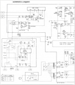
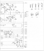
Q615 and Q617 are the drivers whose bases are kept apart by Q613 the vbe multiplier. VR601 is the pot that should make the idle current on the output transistors something reasonable like 10 ma. If you can find an adjustment that makes that so, I'd replace the pot with a fixed resistor of similar value. You may have to parallel two standard value resistors to get a matching value.
The PA amps I own don't use idle bias pots. Ones that are respected as long lasting, repairable, are not very cheap even blown up "for parts or repair".
Other features I don't like, TA7324 is unpurchaseable except as counterfeits. 0.22 ohm emitter resistors on the output transistors gives maximum peak watt rating, at the risk of thermal runaway. My PA amps use 0.5 ohms emitter resistors which are more conservative.
Last edited:
One thing I noticed here, is your schematic has the golden key to figuring this out - voltage readings everywhere. If you are getting zero idle current, and the amp sounds bad, then this means you are operating in Class B mode, and hearing the output transistors switch on and off every time the signal crosses zero. Assuming you have tried to adjust idle current, and cannot, this is caused by a fault in the circuit, and your best starting point is comparing the voltages shown on the schematic to what is going on in the amp. I wouldn't be surprised if you find a bad transistor, open or bad resistor, bad trace, open connection, bad electrolytic capacitor, etc. You may want to put a DMM across the pot's terminals and make sure it varies like it should too.
Last edited:
so i switched the amp on without anything connected to it.
when i first turned the amp on the left channel measured 71 and right 39, then after about 5 minutes the left was 13 and right 47.
i think my pots are the wrong type or faulty, last night i connected a pot to my multi-meter and watch the resistance slowly climb, over the course of an hour i have to adjust the multi-meter because the readings went out of range. i got a pack of 5 vishey T93 from RS-online.
my pots are 5K rated to 1 Watt, should i have used a pot with a lower wattage rating ?
The main problem of higher pot watt rating is making the package fit in the space provided.
Don't understand if the readings in post 30 are millivots out of the speaker jack, or millivolts across the output transistor emitter resistors.
If the first, those readings are okay.
Don't understand if the readings in post 30 are millivots out of the speaker jack, or millivolts across the output transistor emitter resistors.
If the first, those readings are okay.
Are You saying after an our the pot solo connected to the DMM was giving bad readings ?last night i connected a pot to my multi-meter and watch the resistance slowly climb,
That's strange. That pot is probably faulty. It shouldn't vary in value except for the tolerance rating perhaps. Try adjusting BIAS connecting a standard potentiometer insulated instead. Are You measuring DC at the speaker terminals ? A dirty relay contact or a loose wire can give You bad readings. Wiggle the wires and check if they change readings.
@ indianajo
i took the reading from the speaker outputs +&-
@maaco
i purchased a packet of 5 pots, i put one in a bread board and connected it to my meter. would it be helpful for me to post a video. ?
gaz
i took the reading from the speaker outputs +&-
@maaco
i purchased a packet of 5 pots, i put one in a bread board and connected it to my meter. would it be helpful for me to post a video. ?
gaz
Any DVM will do that on low ohms if the battery is failing.
Increasing value is not a syndrome of 99.999% of pots. Some cheap meters will do that. My $39 capacitance meter will do that sometimes. I had a $1 harbor freight meter belonging to my co-worker read unbelievably high on ohms, which lead us to do 3 hours of unnecessary work removing a solenoid from a chest. I bought a $45 farnell meter to use down there which has worked okay. My $29 sears craftsman DVM has been reliable as long as the battery is up, but they started sourcing all their tools from ***** and I don't recommend Sears tools anymore. Harbor Freight with a former name for quality.
Increasing value is not a syndrome of 99.999% of pots. Some cheap meters will do that. My $39 capacitance meter will do that sometimes. I had a $1 harbor freight meter belonging to my co-worker read unbelievably high on ohms, which lead us to do 3 hours of unnecessary work removing a solenoid from a chest. I bought a $45 farnell meter to use down there which has worked okay. My $29 sears craftsman DVM has been reliable as long as the battery is up, but they started sourcing all their tools from ***** and I don't recommend Sears tools anymore. Harbor Freight with a former name for quality.
Last edited:
my multi-meter was £10, and i've had it for a while. perhaps i'll change the battery in it , and treat myself to a new better quality one.
gaz
gaz
ps jo
why didnt you just write china? its no secret, everyone knows most of there stuff is rubbish. 🙂
why didnt you just write china? its no secret, everyone knows most of there stuff is rubbish. 🙂
ps jo
why didnt you just write china? its no secret, everyone knows most of there stuff is rubbish. 🙂
My two Fluke meters are the only way I test things seriously, and accurately.
Fluke has been the professional's choice for a long time.
ps jo
why didnt you just write china? its no secret, everyone knows most of there stuff is rubbish. 🙂
Some people are afraid to speak up.... politically correctness and all that garbage.
Some states have thousands of employees assigned to offensive net warfare. I'm trying to make it a little difficult to be assigned a target value.
Farnell Tenma test equipment comes from the same place as everything else, but checking them with zener diodes, fresh batteries, & 1% resistors from vishay for example, I find their equipment accurate. I've concluded Farnell corporate QA checks pretty seriously. I bought the Tenma DVM with 3 1/2 digits 6 resistance ranges and 5 voltage ranges. I had to buy a good meter for work, that Harbor Freight meter cost us 2 days. Toting a DVM around in a bicycle bag is hard on it, the displays will break and rain can get in.
Warning, almost all DVM produce random numbers on music on the AC scales, except 50-60 hz sine waves. Fluke RMS meters are accurate on music up to 7000 hz, but will totally miss ultrasonic oscillation. Not worth the $160 IMHO. I use a Simpson 266XLPM Analog VOM for music measurements. with a series capacitor to the speaker return terminal. Will easily indicate a 1 mhz oscillation. Unlike oscilloscopes, no electrolytic caps to dry up. Just put ~20 ecaps in a B&K 2120 scope for hum patrol, after spending 2 days scraping glue off to get the boards out. Now the sweep works, will probably blow the vertical amp the next time I use it, since there are still 30-50 e-caps in there.
No, I'm not spending $$$ to ***** to buy anything they make, expecially a new scope. These e-caps I buy are 90% assembled somewhere else.
Last edited:
- Home
- Amplifiers
- Solid State
- capacitor electrolyte= super glue ?