As the title says, read here ( http://www.diyaudio.com/forums/subwoofers/186747-3rd-order-sealed-series-cap.html#post2533376 ) for the sake of lossing a couple of db effeciency, this actually sounds much better on my sub. I was always a firm believer that direct coupled (when possible) was always better than capacitor coupled, but in this case definatly not, the advantages far out-weigh the disadvantages of a cap in the siganal path.
Cheers George
Cheers George
What cap option did you end up using?
Did you try DC bias?
Did you try a film bypass?
(glad you were able to make it work)
Did you try DC bias?
Did you try a film bypass?
(glad you were able to make it work)
Last edited:
I bought 4 x of these old nos non-polarized Spragues to get 2400uf per channel, bought them up slow and discharged a few times to condition them then tested them and got 1220-1240uf each on all 4, sounded even tighter than the crap electros I put back to back.
2x 1200uf 75v NP +-20% Sprague axial capacitor (eBay item 280463446647 end time 06-May-11 14:11:31 AEST) : Business Industrial
Cheers George
2x 1200uf 75v NP +-20% Sprague axial capacitor (eBay item 280463446647 end time 06-May-11 14:11:31 AEST) : Business Industrial
Cheers George
I do this with my full range speakers at a higher frequancy (take the -3dB from 90Hz to 65Hz) and it works well. However you need to design the box to be smaller than usual such that it has a bump in the frequancy response for you to flaten out. If the system Q is <0.7 then you will increase the -3dB point. Also you are sacrificing some efficiancy compared to a box large enough to have the -3dB point you are equalising to. In addition to this the large signal AC distortion perfomance of electrolitics is poor in comparision to to typical audio amplifiers, however better than most speakers. Personaly I prefer doing this to porting but would rather have a larger box if posible.
AJ-Horn shows this type of response and impedance tradeoff
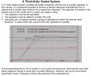
- B&C 15" woofer w. 450uF
- B&C 15" woofer w. 450uF
An externally hosted image should be here but it was not working when we last tested it.
It looks to me in the graph above that a cap in series (which I believe is call a 3rd order sealed enclosure) gives a double impedance hump similar to a ported design?
Mine thankfully has already been worked out by ACI for 2500uf, but what is the formula for getting the right value cap for other woofers and box sizes?
Cheers George
Mine thankfully has already been worked out by ACI for 2500uf, but what is the formula for getting the right value cap for other woofers and box sizes?
Cheers George
Attachments
9th April 2011, 10:21 PM #2
The principle is sound.
"However you need to design the box to be smaller than usual "
The idea is you have a high Qtc (above 1.4 or so) sealed alignment. This will have a big impedance peak at Fb. The left side of the peak is largely inductive, the right side is capacitive.
The capacitor is tuned to the left side a bit below the peak. This causes the impedance at the resonant frequency to drop to 0Ω plus the DC resistance of the voice-coil. It makes the coil draw more power at its resonant frequency, thus playing louder.
I think it best implemented with high ripple current polarized power supply type capacitors, with small audio grade types in parallel to trim to the desired value. The polarized caps are to be just under twice the desired value and hooked up back-to-back with a 1MΩ pull-up resistor to a 9V battery (after Infinity, JBL, etc).
"what is the formula for getting the right value cap for other woofers and box sizes?"
The basic idea has a brief mention in one of the early Loudspeaker Design Cookbook, it may be in the newer versions as well.
With some thought it should be obvious that with a normal impedance of X, and an impedance of 2X just below resonance, that the total amount of boost available is 3dB.
This assumes that the capacitor is of high enough quality to allow the combination to go to 0Ω at the resonant frequency of the capacitor and the inductive reactance of the woofer.
The higher the Qtc is to start with, the higher the impedance peak will be available to get our boost from. It should be obvious that we must resonate out capacitor to the left side of the impedance peak at Qtc (the inductive side of the impedance). The closer the boost frequency is to the resonance at Qtc the more loss there will be at Fb (because you are no longer at resonance with the capacitor and it acts like a voltage divider because the impedance is resistive at Fb and capacitive above Fb).
If this will be a two-way with midrange coming from the bass driver (or a full-range driver with treble from the same unit), then you will want a good quality film cap in parallel with the bass boost cap. It may be advantageous to try battery bias if using back-to-back electrolytics.
Though it might seem like a brilliant idea to size the output cap in a capacitor coupled amplifier as the resonating cap for our use, I tried this in 1997 with a two-way driver and it doesn't seem to work in practice. I also tried to substitute a line operated DC supply for the battery DC bias and found it injected a small amount of power supply hum into the system.
There is a equation for this but there is a problem with constant that depends on the inductance of the speaker. So for low inductance speakers K= 316 000 for really high inducance subwoofer type speakers K= 100 000, for normal woofers use K= 265 000
C= K x Qb/Re x Fb.
These kind of things throws a spanner in the work for a armchair designer. I find it best to be armed with a bunch of 100 µF caps and parallell as much as needed. At least 90% if not closer to 100 % of all systems will work with capacitance in the range of 300- 1000 µF. Parts_express 220µF is 2.88 USD each, if you look at the Dorspen thread you get the graphs as well.
In july 2010 there was interesting paper in JAES by the late A.N. Thiele where he showed practical dimensioning of such 3rd order closed boxes.
Regards
Charles
Regards
Charles
It works in practise as well
http://www.diyaudio.com/forums/multi-way/228670-one-bc-homage-classic-vintage-design-2.html
http://www.diyaudio.com/forums/multi-way/228670-one-bc-homage-classic-vintage-design-2.html
- Status
- Not open for further replies.
- Home
- Loudspeakers
- Subwoofers
- Capacitor coupled bass can sound tighter and go lower in frequency.