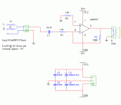
OOPS.
sorry, pin 8 is virtual ground.
Pin 7 is nearly gound. The voltage across r6 separates it from actual ground.
It's nice to see you correcting us, it means you are progressing.
The current into and out of the input pins is the input offset currents.
The voltage generated as these offset currents pass across any resistors sets up a voltage. This voltage is amplified by the gain of the amp and appear at the output as output offset.
The input offset currents cannot pass DC blocking caps. So any route that has a DC blocking cap is removed from the formula. The formula is correct. It's the application of the formula that is flawed.
There is an exception but it is normally so insignificant that it is ignored. The DC blocking cap has an inherent leakage and this is equivalent to a resistance. But, I suspect that allowing for this leakage current will be fruitless except in very high impedance (and necessarily low offset current) FET input stages.
Very interesting...
So the little summing resistors left of the DC cap can be ignored from the gain formula yet they're effective for channel isolation? That would be like having my cake and eating it, too...sounds too good.
So thanks, Nordic and AndrewT. I guess I need to be careful when picking a uF value for the DC input cap in relation to the resistor to the right of it (R3) to make sure that the cutoff is not high enough to block the bass.
is not the same asThe resistor value AFTER the final DC blocking cap affect the high pass filter.
So the little summing resistors left of the DC cap can be ignored from the gain formula yet they're effective for channel isolation?
AndrewT:
Your juxstaposition of statements is meant to either teach me a lesson or just get me to clarify what I think are already well constructed sentences...fun 😀
OK...I think I know the answer to the second question...ALL RESISTANCES MATTER as far back as the eye can see for gain formulas.
I still am wondering about the first question though so I'll re-phrase it again...now in multiple choice format for your enjoyment 😀
Q- When using Nordic's handy little high pass filter calculation applet to figure out the proper value for the DC blocking cap C1, which resistance(s) do I consider?
a- the resistor between the cap and the inverting input pin (R3)
b- the resistors "outboard" of the cap (the summing resistors)
c- all resistors
d- Carlos should stick to accounting
e- none of the above
Hi C,
D sounds nice but I could not face the wrath of your clients were I to set you loose on them.
A will do.
For gain the total series resistance is used.
Gain and filter are two completely separate calculations.
D sounds nice but I could not face the wrath of your clients were I to set you loose on them.
A will do.
For gain the total series resistance is used.
Gain and filter are two completely separate calculations.
- Status
- Not open for further replies.
