Another way to phrase the question might be,
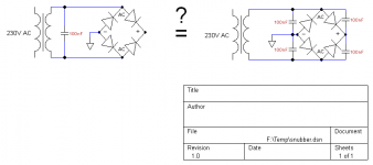
Please may I have your comments and suggestions about the simulation circuit I created (Figure 3). I want to use LTSPICE + Figure 3 to help me understand whether the circuit in Figure 1 provides equivalent amounts of snubbing / ringing reduction, as the circuit in Figure 2.
Please may I have your comments and suggestions about the simulation circuit I created (Figure 3). I want to use LTSPICE + Figure 3 to help me understand whether the circuit in Figure 1 provides equivalent amounts of snubbing / ringing reduction, as the circuit in Figure 2.
I am not skilled enough to make such analysis in LTSpice. But from various schematics of audio amplifiers I have seen, the first variant on the left is more common.
Not exactly. My understanding is that the snubber capacitor protects the diode and does its job best if it's across the diode and not elsewhere. Of course you could also just use rectifiers with a higher reverse voltage rating and cope with any noise problem by filtering, shielding, good wiring practice etc. There are lots of good articles on the web just waiting for your google.
each diode creates switching noise so each should have it's own snubber. Also it will help with ringing to place a small resistor in series with each capacitor to dampen the resonant energy, ~10R.
left variant - is cost saving but need capacitor with enough AC working voltage, right one -more reasonable and need capacitors with less AC working voltage.
P.S. I never use them, I think it is better to use low freq. diodes and do not use snubber ( or what is the name) instead than using high freq. diodes without any understanding why you use them and then try to remove all ringings and so on.
P.S. I never use them, I think it is better to use low freq. diodes and do not use snubber ( or what is the name) instead than using high freq. diodes without any understanding why you use them and then try to remove all ringings and so on.
Capacitors are NOT snubbers.
The capacitor changes the oscillation frequency and limits the amount of current flowing.
The (missing) resistor is the snubber. The resistance absorbs electrical energy and emits it as heat. It's that absorption of electrical energy that Snubs, or damps, the oscillation.
The capacitor changes the oscillation frequency and limits the amount of current flowing.
The (missing) resistor is the snubber. The resistance absorbs electrical energy and emits it as heat. It's that absorption of electrical energy that Snubs, or damps, the oscillation.
The first thing to do is see whether the circuit will be generating significant 'switching spikes'. If the circuit consits of a mains transformer and normal (mains frequency) rectifier diodes I am not sure that snubbers (with or without significant resistance) will be required. I thought there was an earlier comment to that effect but I don't see it now.
Three different issues:
1. transformer inductance ringing - for this the two circuits are equivalent, as both place some capacitance across the transformer secondary. The transformer resistance will provide some damping.
2. diode stored charge recovery - for this the two circuits are different.
3. hum modulation (when the equipment includes an RF oscillator) - for this the two circuits are different.
So the answer depends on exactly what question you are asking.
PS Don't confuse these capacitors with the reverse-voltage-sharing capacitors sometimes used when diodes are wired in series to get a higher PIV. In the simple bridge there is no reverse voltage sharing to consider.
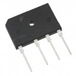
Yes. A bridge is a bridge, however it is packaged.
NB caps are not snubbers. As I said, you need to be clear what it is you are trying to achieve.
NB caps are not snubbers. As I said, you need to be clear what it is you are trying to achieve.
There is a nice article on power supply rectifiers and snubbers at: Power Supply Design: Diode Recovery EMI A little bit of searching found it, there are probably other equally informative sites.
I redid the layout and schematic of the power supply portion. I combined the cap board and the soft start board. Here are the sch and layout. Does anybody see any glaring issues with the layout? Should this be "clean" assuming I also redo my amp board layout?
An externally hosted image should be here but it was not working when we last tested it.
An externally hosted image should be here but it was not working when we last tested it.
- Status
- Not open for further replies.
- Home
- Amplifiers
- Power Supplies
- Capacitor across diodes