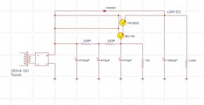
Could somebody check this schematic for a Capacitance Multiplier PSU?
I drew it after reading the article on Capacitance Multipliers at ESP:
http://sound.westhost.com/project15.htm
If I got it right, its the single-ended version of Rod Elliott's design in figure 3.
I want to see how it sounds on the amp I built in this thread.
http://www.diyaudio.com/forums/showthread.php?s=&threadid=111775
Attachments
Hi,
Superficially, your result looks to be the same as (the positive half of) that taken from Rod Elliot's site, unless I have missed something here.
However, there is no need to have 2 separate connections between the + terminal of the bridge and the collectors of the 2 transistors, as you have shown. These 2 traces are simply in parallel with each other.
Regards,
Bobken said:...However, there is no need to have 2 separate connections between the + terminal of the bridge and the collectors of the 2 transistors, as you have shown. These 2 traces are simply in parallel with each other.
Regards,
Thats right, thank you for pointing that out.
- Status
- Not open for further replies.