I think Carlos has a nice implementation, dropping voltage around the cap multiplier, using zeners with enough voltage drop so that peak outputs drawing the rails down do not go low enough to affect the front end of his amps... (HRII and Precision 1)
The much simpler way of looking at 'capacitance multipliers' is this:
It's a brute-force RC low pass filter, with an emitter-follower bolted on to make the filter output a usefully-low impedance. That's all!
It's a brute-force RC low pass filter, with an emitter-follower bolted on to make the filter output a usefully-low impedance. That's all!
AndrewT said:yes, I do mean that when the output AC current becomes significant that the ripple in the rail current becomes worse. To the point that at the highest ClassA output current the rail current can drop to near zero.
I've had a bad few days, when I'm more alert I'll try and get my head around this apparent violation of Kirchoff's current law.
jnb said:Where I see that this discussion of current in class A amps culminates is that if you can eliminate ripple at quiescent conditions, then you've pretty much got the problem licked.
Another view of the capacitance multiplier is as a voltage regulator. If you look at the reference volage created by the dummy resistive load, it remains fairly constant with all but long term perturbations.
martin clark said:The much simpler way of looking at 'capacitance multipliers' is this:
It's a brute-force RC low pass filter, with an emitter-follower bolted on to make the filter output a usefully-low impedance. That's all!
IMO, the capacitance regulator isn't that great...with a few more parts, you can make a fixed reference series-regulator (as opposed to the cap multipliers simple 'filtered reference'). I've done it, works great, astonishingly low ripple, no additional caps..
What did you use as a reference? I found that with zener voltage changing with current draw from the base of the pass transistor/driver, it din't fare well against the standard RCRCRC, which is a reference once you get away from DC.
jnb said:What did you use as a reference? I found that with zener voltage changing with current draw from the base of the pass transistor/driver, it din't fare well against the standard RCRCRC, which is a reference once you get away from DC.
I've found that if you're going to use a BJT for a pass-device, a darlington is the way to go. Much lower base current, then the zener fairs pretty well. Use small caps across the zener to reduce noise. (they are noisy), and use near the highest supply resistor you can to get away with but still drive the zener on it's intended voltage and the base of the darlington, that way there will be the least amount of ripple on the zener.
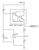
The other way, and better way I think, is to sample the output with a shunt regulator (i.e. TL431 -> http://focus.ti.com/lit/ds/symlink/tl431.pdf). Use a resistive divider so that Vref=2.5V @ your output voltage. These will work with an output voltage up to about 30V. See attached circuit.
With increasing complexity, the circuit can be made to handle higher voltages. But it will still likely be cheaper than high value high voltage caps. It can also be made to, with a few tricks, have a really low drop-out voltage.
Attachments
- Status
- Not open for further replies.