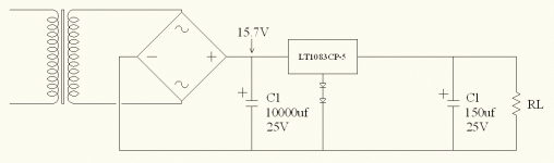
So I'm trying to dial in the value of R2 that will give me my desired voltage for filaments in the following setup.
Because I've got the LT1083 data sheet in front of me (it's also here), I do the math and dial up what I think will be the appropriate value for R2. RL is the actual paralleled filaments I'l be using (6.3V, 3.3A). I dial up the VARIAC slowly and monitor voltage. I cannot get up to full voltage on the VARIAC in spite of adjusting R2 - the output voltage will far exceed the 6.3V I need. I also notice the monitored output voltage is bouncing around. I shut down and replace make RL a rheostat and try again. This time I can bring the VARIAC up to full voltage, but as I dial the rheostat to increase the load to the 3.3A I will need I notice the voltage starts bouncing around again when I get to around 2A - nowhere near the 7.5A limit of the LT1083. What am I doing wrong?
An externally hosted image should be here but it was not working when we last tested it.
Because I've got the LT1083 data sheet in front of me (it's also here), I do the math and dial up what I think will be the appropriate value for R2. RL is the actual paralleled filaments I'l be using (6.3V, 3.3A). I dial up the VARIAC slowly and monitor voltage. I cannot get up to full voltage on the VARIAC in spite of adjusting R2 - the output voltage will far exceed the 6.3V I need. I also notice the monitored output voltage is bouncing around. I shut down and replace make RL a rheostat and try again. This time I can bring the VARIAC up to full voltage, but as I dial the rheostat to increase the load to the 3.3A I will need I notice the voltage starts bouncing around again when I get to around 2A - nowhere near the 7.5A limit of the LT1083. What am I doing wrong?
The schematic shows a LT1083CP-5 which is a 5 volt fixed regulator. You should be using a LT1083CP which is adjustable. The power dissipation in your application is (15.7-6.3)*3.3= 31 Watts. Use a BIG heatsink.
Are you using the fixed 5-volt version of the LT1083 as shown in your schematic? I've used that trick in the past for "LM" series regs, but the "LT' types are a different topology, don't know if it works with them, might be wiser to use the variable output version. Beyond that, is your chip mounted to enough heat sink? You're asking that chip to dissapate over 30 watts, which is a LOT! You may have to go with a lower voltage transformer to bring total power dissapation down. I also recommend using protection diodes for the chip, cheap and easy peace of mind. Problem could also be a bad component. Does it regulate at all, like when lightly loaded? If not yuo may have a bad chip.
Hope this halps. Good luck.
Hope this halps. Good luck.
See, there's the importance of putting component values on uploaded drawings - I do in fact have a CP-5 (ie, fixed) version of the reg. Loser! I will also attempt to use a lower input voltage. Thanks guys.
- Status
- Not open for further replies.