Hi Folks;
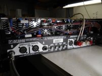
A 75 lb power landed on my bench in rough shape. It is rated at 1250 Watts per chan into 8 ohms! The protect light is on but chan B is working fine. Chan A has 8 VDC on speaker terminals with no load, about 300 mV with an 8 ohm load connected . There is a momentary buzzing sound coming from the rear of the amp itself, after switching off.
looking for a little guidance before 'ripping' into it. It seems to have (protection?) Triacs across the outputs but if there is a shorted output and the triac is shunting the B+/- from the speaker, would something be smoking now?
Thanks, puzzled Peter in Canada
Attachments
Service manual:
Yorkville Legacy Products "Downloads"
At the end: a service bulletin telling of a fault "that will eventually affect every unit shipped before February 26th, 2000."
Yorkville Legacy Products "Downloads"
At the end: a service bulletin telling of a fault "that will eventually affect every unit shipped before February 26th, 2000."
i've not worked on many and most where simply input connector troubles, to your question about the protection i think it's "flying rails" so if the triac is triggered the B+ collapses.
I will check C26, thanks. This will be an expensive project; multiple T-03's shorted in several banks!
But amps of this magnitude are definitely worth repairing. And at least it’s possible without needing $400,000 worth of lab equipment just to properly diagnose (linear not switch mode, at this power level it can be problematic). Worst that can happen is replacing an entire set of 21193/4 - expensive but not THAT expensive.
If it is a flying rail amplifier (probably), There are more things that can cause DC offsets than with traditional common ground amps. Some of them quite simple, but can be tricky if you’ve never dealt with them before.
Is the transformer reasonably quiet in this one, or will you be dipping it too?
If it is a flying rail amplifier (probably), There are more things that can cause DC offsets than with traditional common ground amps. Some of them quite simple, but can be tricky if you’ve never dealt with them before.
Is the transformer reasonably quiet in this one, or will you be dipping it too?
Hi wg_ski;
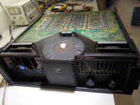
The transformer IS quieter than the Crest (was). It is actually 4 amplifiers, 2 class H amps per channel, permanently bridged. Seems to me to be a lot of output devices in series.
It is worth fixing but I may chicken out of this project. One screw up and there goes a fresh set of 21195's and 96's (24 per channel)
If any output is dead all will need replacement as well
As the drivers and rail switching transistors and diodes
This is because of the high rail voltages and currents will destroy them when an output shorts.
As the drivers and rail switching transistors and diodes
This is because of the high rail voltages and currents will destroy them when an output shorts.
Hi
One of the first checks on a solid-state amp is DC at the output. If any is present DO NOT connect a speaker until repairs have eliminated the cause of the DC.
Always use a power limiting safety socket (light bulbs) to do initial testing of any device for test.
Solid-state amps can often pass a clean sine wave with no load but then show their faults with even just a 1k load. BJT failures tend to show up more on dynamic tests rather than static ones, unless the device is outright shorted.
The amp does not have "flying rails"; rather, a simple three-tier class-H PA. There is a switch for low-z and high-z that changes a tap on the primary so that the secondaries will be higher or lower.
Each output stage only has three pairs of the MJLs, plus the mosfet rail switches. Not expensive to replace but a lot of labour to do it.
What IS floating is the drive circuitry for the MJLs. Since about 1984 Yorkville has used variations on this scheme in a few bass amps and in the Audiopro PAs. The floating driver is powered from the look-ahead supply that turns on the rail switchers, and can be either discreet or opamps. In the subject amp it is opamps.
PS - LOVE your avatar, Peter S
Thanks, the avatar has been my boss for 27 years! I had assumed this amp was two, two-tier class H amps, permanently bridged.
Here is the schematic. Tests were performed in accordance with your methods. I have powered-up amplifiers with only drivers, no outputs. Could I do this with this amplifier?
Each channel seems to have 2 class H amps, labeled A and B. I will check to see if both A and B sections are fried.
Pardon my ignorance but are Q25 and Q26 the drivers? (In a darlington configuration with Q23 and Q24?)
Here is an edited schematic;
Attachments
Last edited:
It does appear to be two 2-tier class H amps per channel. The mosfets are the drivers for the upper output banks. It is a non switching design, where the upper output banks only operate when more than 42(ish) volts is demanded. Sort of like the predecessors to your CA18. The driver circuit is a little less straightforward, but not impossibly so.
You can *almost* run this one output-less during testing, but not quite. If you look at the driver pair, the resistor goes directly between the two emitters and does not tie to the output rail like most amps do. You would need to hang a 39 ohm resistor from base to emitter of one of the empty output transistor positions on both the + and - sides first. If you don’t, there is no output current path. The upper bank already has this. When doing this, do not operate without any load at all - the gate-source of the upper driver mosfet will have nothing to discharge it and it may not switch the upper rail off at all. It probably won’t hurt anything, other than not being able to verify the transitions to and from the upper rail. Use a dummy load of several hundred ohms. I made that mistake during development of a big class H and wondered why my rail switches were so slow to turn off. Put even the slightest load on it, and the waveform squared right up.
You can *almost* run this one output-less during testing, but not quite. If you look at the driver pair, the resistor goes directly between the two emitters and does not tie to the output rail like most amps do. You would need to hang a 39 ohm resistor from base to emitter of one of the empty output transistor positions on both the + and - sides first. If you don’t, there is no output current path. The upper bank already has this. When doing this, do not operate without any load at all - the gate-source of the upper driver mosfet will have nothing to discharge it and it may not switch the upper rail off at all. It probably won’t hurt anything, other than not being able to verify the transitions to and from the upper rail. Use a dummy load of several hundred ohms. I made that mistake during development of a big class H and wondered why my rail switches were so slow to turn off. Put even the slightest load on it, and the waveform squared right up.
Thanks wg_ski for taking the time. I would not have realized this issue. How about this, (at the risk of testing your patience). Not every output appears to be blown. How about leaving one output in each position? It seems there may be shorted devices in both A and B amplifiers. If I could find 4 good MJ21195's and 4 96's would that be a safe way to bring up the amp? I will test drivers in circuit and use 200? dummy load.
Yes, using only one output per bank is a safe and accepted way of bringing up amps in this condition. If there are some blown and some not, you can probably find enough. And if not go grab a couple of spares, even if they are something like a 15024. It’s a good use for the “leftover” parts after matching a bank on a previous rebuild. This way it will drive say a 10 or 20 ohm load and be able to exercise the bias adjust.
If you have some in a bank that are shorted, I’d consider the rest “suspect” and not use them in the final rebuild. Perfectly ok for the limited population test.
If you have some in a bank that are shorted, I’d consider the rest “suspect” and not use them in the final rebuild. Perfectly ok for the limited population test.
Hi
O'm surprised I never noticed this amp as it has been out since 1999. It is 2-tier and bridged as the OP said. It uses MJLs as the rail switchers just as the very first high-power AP-series amp did (AP4020) - a logical evolutionary step and one that the hifi superamps all follow to be able to get high voltage swing across the load. Where the model in question has +/-100V rails, AP4K has 175V rails to draw from.. My previous post referred to the SE configuration (AP4K) which has 3-teirs and the same number of parallel paths in the output stage as the AP6040, so overall much simpler.
My experience fixing solid-state amps suggests a brute force repair is safest. if one output device fails the others will try to take the load and can be damaged, and this extends to drivers and predrivers. I would not mix old and new devices as the amp could come back with the customer thinking you did nothing the first time around.
- Home
- Amplifiers
- Solid State
- Canadian Monster Yorkville AP6040