Can someone please explain (guess?) what the tubes function is in this schematic ? Sold as a preamplifier but heard rumors its just a buffer....Would love to know the truth from someone who can read such things !
Any help appreciated 🙂
* Darn that's only part of it - I'm sure I had a full schematic somewhere....I'll have a look...
Any help appreciated 🙂
* Darn that's only part of it - I'm sure I had a full schematic somewhere....I'll have a look...
Attachments
Last edited:
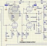
I think it's an SRPP that's drawn incorrectly. The gain of each SRPP stage is fairly high but the overall gain of the circuit is set by the global negative feedback.
If my assumption of a schematic error is false and it's not an SRPP, then I'd like to know what the idea is behind the top tube with zero bias.
~Tom
If my assumption of a schematic error is false and it's not an SRPP, then I'd like to know what the idea is behind the top tube with zero bias.
~Tom
Ok, so what is the bias on the top tube?
How much current passes?
Therein lies the answer?
_-_-
but yes, I agree it may be an incorrectly drawn srpp...
How much current passes?
Therein lies the answer?
_-_-
but yes, I agree it may be an incorrectly drawn srpp...
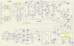
notice also the tube stages are AC coupled but there is nothing that keeps the output at OVDC. I see two adj pots for the idle and one to set the output to ovdc but there is no Dc feedback to keep it there.
Looks like two SRPPs with poorly done schemos. If they literally meant to connect the grid and cathode together, then the tube on top becomes nothing more than a diode, and the only thing that will act to provide any voltage gain is the dynamic plate impedance of that diode, which won't amount to very much gain at all.
If that was the intent, then it's possible that it's using the nonlinear diode characteristic to compensate the transistor nonlinearities. However, I highly doubt this was the intent as there is no VAS between the hollow state front end and the solid state back end, therefore, no useful gain at all, and definitely not enough to support gNFB.
If that was the intent, then it's possible that it's using the nonlinear diode characteristic to compensate the transistor nonlinearities. However, I highly doubt this was the intent as there is no VAS between the hollow state front end and the solid state back end, therefore, no useful gain at all, and definitely not enough to support gNFB.
Thanks for the hep guys 🙂
So from what I can gather it IS a pre-amplifier which either has a poor design or incorrect schematics...
FWIW The model is : Yaqin VK-2100 if your interested.
Thanks again.
So from what I can gather it IS a pre-amplifier which either has a poor design or incorrect schematics...
FWIW The model is : Yaqin VK-2100 if your interested.
Thanks again.
So from what I can gather it IS a pre-amplifier which either has a poor design or incorrect schematics...
Or, most likely, both.
Or, most likely, both.
Indeed, It sounds like ****
Loads of power but its so brash....Sounds like a PA amp.
The top triode has grid and cathode connected together, it is simply a zero biased triode, acting as a nonlinear resistor load, to partially cancel the nonlinearity of the lower triode. Consider the cathode follower half of the Aikido, when used as a headphone amp, some people bypass the cathode resistor in the lower half to reduce output impedance, effectively making the lower triode a nonlinear resistor. It is similar in this case, just in the plate circuit instead of cathode. Nothing out of ordinary.
It is interesting that the amp has two identical stages in each channel. It could be a marketing ploy to increase tube count, but the 1K5 plate resistor seems to suggest that the designer originally intended to simply add a SRPP stage to make a hybrid out of a solid state amp, but the phase was wrong for feedback, so he just added another stage to inverse the phase. The gain is probably too high with both stages, so the top triode is re-wired as a nonlinear resistor to reduce the gain. Just my WAG.
It is interesting that the amp has two identical stages in each channel. It could be a marketing ploy to increase tube count, but the 1K5 plate resistor seems to suggest that the designer originally intended to simply add a SRPP stage to make a hybrid out of a solid state amp, but the phase was wrong for feedback, so he just added another stage to inverse the phase. The gain is probably too high with both stages, so the top triode is re-wired as a nonlinear resistor to reduce the gain. Just my WAG.
So from what I can gather it IS a pre-amplifier which either has a poor design or incorrect schematics...
The complete amp is a power amp. The two tubes in the front could form a preamp, but why use two SRPP's as a preamp? If you want an SRPP-based tube preamp, I suggest looking at the Aikido. There are plenty of clones out there.
If the design is to be used as is (as a hybrid power amp), I'd scrap the output stage and design something better.
~Tom
Okay thanks, I'll sell it on easily enough what with it using tubes 🙄
Ideally I want a good EL84 amp but with a budget of £300 that's easier said than done ! .... Unless buying vintage but they will all need a full restoration by now.
Oh well, Thanks again 🙂
Ideally I want a good EL84 amp but with a budget of £300 that's easier said than done ! .... Unless buying vintage but they will all need a full restoration by now.
Oh well, Thanks again 🙂
- Status
- Not open for further replies.
- Home
- Amplifiers
- Tubes / Valves
- Can you explain what this is ?