Not only tranfer impedande. Considering it as a "black box", making two test you can get all the parameters of a transformer.
One of them is the open secondary test. Leaving the secondary open (only a voltmeter) and giving the primary full rated voltage at rated frequency, you can get voltage ratio(s), magnetizing current (from its value you can obtain core loses, primary inductance, etc.). In general, magnetic loses.
Maintaining the secondary shortcircuited with a proper ammeter as only load and increasing the primary voltage from zero to such a value so that the secondary current is the full rated current, you obtain copper loses, leakage inductance, etc. In general, copper related looses.
This is how large power transformers and ac and dc motors are evaluated without wasting full power in them (Motors are considered as transformers, testing them with the shaft free or blocked). In all cases, only a few percentage of the full rated power is needed in the laboratory. We made such a tests in the university at a cathedra called "Máquinas Eléctricas I & II" (Electric Machines) when I studied at UTN the past century, with a profe called Paolillo.

That's nice to know, but I don't know anything about the rated voltages or currents for any of these transformers so I can't really do it like that sadlyNot only tranfer impedande. Considering it as a "black box", making two test you can get all the parameters of a transformer.
One of them is the open secondary test. Leaving the secondary open (only a voltmeter) and giving the primary full rated voltage at rated frequency, you can get voltage ratio(s), magnetizing current (from its value you can obtain core loses, primary inductance, etc.). In general, magnetic loses.
Maintaining the secondary shortcircuited with a proper ammeter as only load and increasing the primary voltage from zero to such a value so that the secondary current is the full rated current, you obtain copper loses, leakage inductance, etc. In general, copper related looses.
This is how large power transformers and ac and dc motors are evaluated without wasting full power in them (Motors are considered as transformers, testing them with the shaft free or blocked). In all cases, only a few percentage of the full rated power is needed in the laboratory. We made such a tests in the university at a cathedra called "Máquinas Eléctricas I & II" (Electric Machines) when I studied at UTN the past century, with a profe called Paolillo.
If you can see the wires; you can then roughly estimate currents having in mind current densities from 2 to 4A/m^2. Thus, having the core at your eyes, you can also estimate power capability. Putting some low voltage in one winding you can measure voltages in others.
Full voltage can be measured having an oscilloscope. Measuring in it primary current integrated through a low pass filter (integral of primary current) and output voltage, the BH loop can be saw (now in doubt if integrating primary current or secondary voltage but one of the is surely). Increasing primary voltage until saturation starts to occur looking o'scope pattern, give you the primary voltage. Also the temperature takes into account. Proper evaluation of several of this parameter give you a crude approximation. Thus, with the test in my previous post finishes.
Imagine you testing a 500KVA transformer at full power !!! Impossible.
Keep in mind that no one transformer has an unique primary, everyone of the windings may be the primary and (obviously) one of them at a time. The othrrs will act as secondaries.
This seems rather odd. A very long time ago I remember building my first few radios using PNP germanium power transistors and a tiny output transformer about the same size (1" cube). Power was low, a few hundred milliwatts into a little 3-inch, 8 ohm speaker, but I don't remember any heat or warmth in the transformer at all.I first set up the test at 1/2W and some wax(???) started boiling out of it the instant the power was switched on...

Let's see. 200mV RMS will deliver 0.8 mW into a 50 ohm load....at 100Hz it's more like 180-200mV. Either way that's practically 0W into 50ohm headphones
That's not much power at first sight, but headphones are extremely sensitive. Ever since Sony invented the modern low-impedance headphones for use with their Sony Walkman in the early 1980s, contemporary headphones will often put out 100 dB SPL when driven with only one single milliwatt of input power!
That means 0.8 mW into typical headphones will deliver 97 dB SPL at your ears. That's very, very, very loud - more than loud enough to permanently damage your hearing!
I built myself a tiny little headphone amplifier last year, for use with a Flamma Preamp so I could play electric guitar without disturbing anyone else. Because tiny amounts of power can destroy your hearing through headphones, I dropped the power supply voltage to the little stereo chip amp to only 2.7 volts DC. That way, maximum peak-to-peak output voltage is only a few hundred millivolts. Accidental pops or bangs are less likely to leave me deaf for life.
Right here on diyAudio, I've seen many headphone amplifier schematics posted, which are designed to run on +/- 15 volts, like an op-amp. These can deliver nearly 3 watts into 32 ohms headphones, which means they can deliver about 135 dB SPL at your ears.
That sort of SPL causes instantaneous, permanent hearing damage. You're deaf after one note. And you'll stay deaf till you die.
In my opinion, using this sort of headphone amplifier is very dangerous. Using one is playing Russian Roulette with your hearing. One accidental loud "pop!" due to a loose input cable could leave you deaf for life.

-Gnobuddy
You could also simply put a 22k resistor in series with the primary, and then drive it from your signal generator, so that the transformer primary "sees" a driving impedance of 22k rather than 50 ohms.So as the secondary is approx. 50r and the signal generator is 50r, if you put the signal into the secondary and place a 21k load in the primary, this would give quiet a realistic measurement of frequency response.
Put a 47 ohm, or 51 ohm (nearest standard values) across the secondary, and measure voltage across that, so that the secondary is also correctly loaded.
-Gnobuddy
Sorry I wasn't clear, that's 200mVpp so 70mVrms => 0.1mW => 10dB(If we assume 100dB/mVrms) so about the sound level of breathing, I'd say that's pretty much no power personally 🙂200mV RMS
Wow that's pretty stupid... Hope someone warned them and they were never built like thatRight here on diyAudio, I've seen many headphone amplifier schematics posted, which are designed to run on +/- 15 volts, like an op-amp. These can deliver nearly 3 watts into 32 ohms headphones, which means they can deliver about 135 dB SPL at your ears.
Good idea, might give this a try to see if the results differ 😀You could also simply put a 22k resistor in series with the primary, and then drive it from your signal generator, so that the transformer primary "sees" a driving impedance of 22k rather than 50 ohms.
Put a 47 ohm, or 51 ohm (nearest standard values) across the secondary, and measure voltage across that, so that the secondary is also correctly loaded.
-Gnobuddy
Agreed, but I belive I have figured out the issue actually. I was just using an adjustable AC source which puts out power at mains frequency, and as established already here the core really doesn't like that so I did a test at about 180mW but at 1kHz and no noticeable heat was created at all! Only the resistor load was any warmer than room temperature after several minutes of testing.This seems rather odd. A very long time ago I remember building my first few radios using PNP germanium power transistors and a tiny output transformer about the same size (1" cube). Power was low, a few hundred milliwatts into a little 3-inch, 8 ohm speaker, but I don't remember any heat or warmth in the transformer at all.
200 mV pp is certainly less than 200 mV RMS, but not that different.Sorry I wasn't clear, that's 200mVpp so 70mVrms => 0.1mW => 10dB(If we assume 100dB/mVrms) so about the sound level of breathing, I'd say that's pretty much no power personally 🙂
Something went awry there. 🙂
200 mV pp = 70.7 mV RMS, agreed.
Power into 50 ohms = 0.1mW, agreed.
0.1mW is (-10 dB) compared to 1 mW, agreed.
Typical headphones put out 100 dB when fed 1 mW of power.
When fed 10 dB less power, the expected SPL is (100 dB - 10 dB). Which is 90 dB, not 10 dB!
To recap: You can expect 90 dB SPL at your ears, from a mere 0.1 mW of power fed into headphones with a sensitivity of 100 dB/mW!
90 dB, as I'm sure you know, is very, very loud. Loud enough to damage your hearing if you listen for any extended period of time.
A lot of professional bass-guitar players used to use a 1000-watt amplifier on stage.
At the other end of the scale, one-tenth of a milliwatt - ten million times less power - is loud enough to damage your hearing if you use headphones!
Isn't that amazing?
-Gnobuddy
Seems most points are covered.
I would never test an unknown transformer without measuring a few things first. Certainly not putting 120V or even 12 V onto a winding.
AS earlier posts suggested, start with the DC resistances. That should give you some idea of operating voltages in that a high resistance would indicate a higher voltage than a lower resistance, but all this is dependent on the power rating of the transformer. It also tells you which connections are connected to which winding and which is supposedly separate, as once a transformer is powered, capacitance effects can couple through.
Has the transformer got an air gap - is it intended for DC current in a single ended output?
Estimate the power rating from the core: a 1 inch section, for example, for an EI shape would give an overall measurement of 3 x 2 1/2 x 1 inch when assembled, excluding the windings. That is a typical 50W rating for mains (50Hz) but less for audio if the frequency response and distortion are to be improved. Perhaps only 20W push pull, or even 5W single ended.
The turns ratio can be measured by applying a small AC voltage to a winding and measuring all the other voltages. AS you now have an the windings mapped out, you can then check for phasing using an oscilloscope. This could indicate, for example, if you had a 44% tapped valve unit for "Ultra-Linear" class A or for mains votlage tappings.
I would not use a variac as (a) the voltage is likely to be too coarse a control and (b) dangerous as it is essentially a path through the live mains feed. I tend to use a power amp and oscillator as you can also use that to test bandwidths. Not DC coupled, an old AC coupled amp is best for this to avoid any possible saturation effects, and even then often with a 8 ohm +1 ohm dropper resistors to prevent resonances (big inductance + big capacitor = LF oscillation possible), feed the transformer from the 1 ohm load.
That also means you can apply suitable load resistors on secondary (or other winding taps) and get an idea of efficiency, bearing in mind that the effecitnve input impedance is about 1 ohm. I typically start measurements at 100Hz, assuming it at least has that bandwidth, but it isn't a fixed value: it is just to see where things are before changing frequencies.
Once you start to get some basic data you can then make some calculations on what you think it is for. A secondary winding for a valve amplifier transformer should have a DC resistance less than a tenth of its nominal impedance - so would be in the region of 0.1 to 1 ohm (depending on power and frequency response etc) and the primary winding may be 10-100 ohms while a mains transformer might have a resistance in the region of 2-20 ohms (depending, so none of these are hard values. High power transformers should have lower resistances while lower power transformers, higher.)
Impedance ratios are turns ratios squared. I'm sure that was pointed out. Example might be for 50W push pull a secondary resistance of 0.1 ohms a primary of 100 (but for 400V operating line) and a turns ratio of 10:1 with an impedance ratio of 100:1 (8k anode load) for example.
You can make some estimate of the inductances too, by measuring the current flows once you have determined what voltages they should be able to withstand. That may be where your 12V or higher is useful. A more useful test however would be the B:H curve. You can measure this approximately using a "simple" RC integrator but you need to take account of the input parameters to make sure the calculation is right. As a clue the normal audio grade iron should saturate around 1.7 Teslas but a low distortion EI unit might run at 1T or less, which would also give you some idea of the operating conditions.
This makes me wonder why you would ever need a headphone amp.... And why I'm building one(well honestly it's a lot of fun to build stuff even if it's fairly useless 😛 )200 mV pp is certainly less than 200 mV RMS, but not that different.
Something went awry there. 🙂
200 mV pp = 70.7 mV RMS, agreed.
Power into 50 ohms = 0.1mW, agreed.
0.1mW is (-10 dB) compared to 1 mW, agreed.
Typical headphones put out 100 dB when fed 1 mW of power.
When fed 10 dB less power, the expected SPL is (100 dB - 10 dB). Which is 90 dB, not 10 dB!
To recap: You can expect 90 dB SPL at your ears, from a mere 0.1 mW of power fed into headphones with a sensitivity of 100 dB/mW!
90 dB, as I'm sure you know, is very, very loud. Loud enough to damage your hearing if you listen for any extended period of time.
A lot of professional bass-guitar players used to use a 1000-watt amplifier on stage.
At the other end of the scale, one-tenth of a milliwatt - ten million times less power - is loud enough to damage your hearing if you use headphones!
Isn't that amazing?
-Gnobuddy
Lots of good tips, thank you!Seems most points are covered.
I would never test an unknown transformer without measuring a few things first. Certainly not putting 120V or even 12 V onto a winding.
AS earlier posts suggested, start with the DC resistances. That should give you some idea of operating voltages in that a high resistance would indicate a higher voltage than a lower resistance, but all this is dependent on the power rating of the transformer. It also tells you which connections are connected to which winding and which is supposedly separate, as once a transformer is powered, capacitance effects can couple through.
Has the transformer got an air gap - is it intended for DC current in a single ended output?
Estimate the power rating from the core: a 1 inch section, for example, for an EI shape would give an overall measurement of 3 x 2 1/2 x 1 inch when assembled, excluding the windings. That is a typical 50W rating for mains (50Hz) but less for audio if the frequency response and distortion are to be improved. Perhaps only 20W push pull, or even 5W single ended.
The turns ratio can be measured by applying a small AC voltage to a winding and measuring all the other voltages. AS you now have an the windings mapped out, you can then check for phasing using an oscilloscope. This could indicate, for example, if you had a 44% tapped valve unit for "Ultra-Linear" class A or for mains votlage tappings.
I would not use a variac as (a) the voltage is likely to be too coarse a control and (b) dangerous as it is essentially a path through the live mains feed. I tend to use a power amp and oscillator as you can also use that to test bandwidths. Not DC coupled, an old AC coupled amp is best for this to avoid any possible saturation effects, and even then often with a 8 ohm +1 ohm dropper resistors to prevent resonances (big inductance + big capacitor = LF oscillation possible), feed the transformer from the 1 ohm load.
That also means you can apply suitable load resistors on secondary (or other winding taps) and get an idea of efficiency, bearing in mind that the effecitnve input impedance is about 1 ohm. I typically start measurements at 100Hz, assuming it at least has that bandwidth, but it isn't a fixed value: it is just to see where things are before changing frequencies.
Once you start to get some basic data you can then make some calculations on what you think it is for. A secondary winding for a valve amplifier transformer should have a DC resistance less than a tenth of its nominal impedance - so would be in the region of 0.1 to 1 ohm (depending on power and frequency response etc) and the primary winding may be 10-100 ohms while a mains transformer might have a resistance in the region of 2-20 ohms (depending, so none of these are hard values. High power transformers should have lower resistances while lower power transformers, higher.)
Impedance ratios are turns ratios squared. I'm sure that was pointed out. Example might be for 50W push pull a secondary resistance of 0.1 ohms a primary of 100 (but for 400V operating line) and a turns ratio of 10:1 with an impedance ratio of 100:1 (8k anode load) for example.
You can make some estimate of the inductances too, by measuring the current flows once you have determined what voltages they should be able to withstand. That may be where your 12V or higher is useful. A more useful test however would be the B:H curve. You can measure this approximately using a "simple" RC integrator but you need to take account of the input parameters to make sure the calculation is right. As a clue the normal audio grade iron should saturate around 1.7 Teslas but a low distortion EI unit might run at 1T or less, which would also give you some idea of the operating conditions.
Oops!
Impedance ratio for 8k:8 ohms should have been a turns ratio of 31.6:1, not 10:1!! (ignoring additional loading allowance).
But I'm sure you worked that out.
Impedance ratio for 8k:8 ohms should have been a turns ratio of 31.6:1, not 10:1!! (ignoring additional loading allowance).
But I'm sure you worked that out.
When I realized I needed a headphone amp to go with my Flamma FS06 (guitar) preamp, I had the same question for myself. What did I really need?This makes me wonder why you would ever need a headphone amp.... And why I'm building one(well honestly it's a lot of fun to build stuff even if it's fairly useless 😛 )
Once I started to think about it, I couldn't see any alternative. I have a couple of different headphones. All have about 32 ohms impedance. To drive one milliwatt into any of these, you need RMS currents around 5.6 mA, or peak currents around 8 mA.
This is just big enough to be a little awkward for most ordinary op-amps, particularly if you decide you want a few dB of headroom to avoid any unwanted clipping. You'd need 16 mA if you wanted another 6 dB of headroom (4 mW).
More importantly, none of the op-amps I looked at are designed to drive a 32 ohm load directly.
A long time ago, it was traditional to put a large resistor (several hundreds of ohms or more) in series with the headphone output jack, and drive it from an ordinary op-amp stage. The series resistor kept the op-amp happy, and controlled peak currents to safe levels - but it also drives the headphone from a high impedance instead of a low one, and this will mess up the headphone's frequency response. I didn't want to do that.
I also wanted to keep DC supply voltage very low to limit the risk of ear-damaging SPL levels. There are op-amps that will run on low supply voltage, but they also tend to be the ones that have less available output current.
The engineering requirements were starting to gel. What I was looking for was a stereo audio chip that was happy driving a 32 ohm load, and also happy to operate on very low DC power supply voltage. It needed to have a pair of 1/4" input jacks to be compatible with any mono or stereo guitar FX pedal out there. It would need a mono/stereo switch for the same reason.
There are a lot of audio electronic devices that run on a single lithium cell, and drive headphones, so there had to be a suitable audio chip out there. I didn't want to deal with soldering an SMD device, so I was really hoping to find a through-hole part (unlikely) or a little breakout board or eval board with the SMD chip already soldered to it.
I found a little Sparkfun eval board for the LM4853 audio power amplifier at Digikey that looked perfect. The chip is stereo, has absurdly low distortion, is tiny, and even comes with a stereo volume pot and on-off power switch: https://www.digikey.ca/en/products/detail/sparkfun-electronics/DEV-14475/8702489
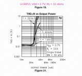
At first glance, output power specs for the Sparkfun "Noisy Cricket" (datasheet from Digikey link above) are dangerously excessive, quoting 1.5 watts RMS output power, which is enough to permanently destroy your hearing in an instant if you use headphones.
Fortunately that turned out to be mostly advertising hyperbole. When I dug into the actual LM4853 datasheet, I found that the chip was rated for operation on as little as 2.7 volts DC, and would deliver about 25 mW maximum output power to a 32 ohm load in this case.
25 mW is enough for 114 dB SPL using headphones with a sensitivity of 100 dB/mW. That's already dangerously high, but maybe acceptable, if used with care. At least you won't go permanently deaf if a bad cable causes a loud pop.
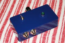
I built the little Noisy Cricket board into a little Hammond die-cast enclosure the size of a small guitar FX pedal, and used another little eval board (a fingernail-sized adjustable DC-DC convertor from Robotshop) to drop the usual 9V pedal power supply down to about 2.4 volts, which was as low as it would go. The LM4853 seemed happy to operate at this voltage, and might work at even lower voltage for additional safety (to your ears!).
Power levels are so low that a tiny little linear (not switching) voltage regulator would have done the job just as well. Maybe better, as there wouldn't be any switching noise. But the little switch-mode eval board works fine, and I can't hear any noise at all in the headphones.
You can see the left and right input jacks in the photo, as well as the mono/stereo toggle switch (it provides the same input signal to both channels if flipped to the mono position, which lets you drive the headphone amp from a mono source, and still hear sound in both ears.) The 1/8" stereo output jack is on the other side of the case.
Attachments
hello all -
I'm looking for a bit of help and insight into a test result of an Sansui AU-111 OPT, which is suppose to be about 5K primary impedance. See the attached screen cap for winding colors. Also know that this OPT uses the CFT windings, apparently 10%.
My test setup to measure primary impedance was to input a signal on the 8 ohm secondary (BLK,BLU) and measure the resulting voltage on the primary (BLU,YLW) then the primary impedance is: (Vp/Vs)^2 x 8ohms.
I used 2 different sources as I wanted to make sure I was getting enough current. First I used a B&K signal generator, lots of drive (20Vpp) into 600 ohms at 1KHz. Then I followed up with a filament transformer (5VAC, 60Hz) Both got the same result.
On the secondary side I brought up the sig gen to 1Vpp. On the primary side I measured 20.5Vpp. Thus, (20.5/1)^2 x 8 = 3.36K. What?!?!
I also measured the primary Z using a B&K 879B LCR meter. With all secondaries open, it measures 4.35K at 1KHz.
The specification for the transformer says it should be about 5K. The 6L6GC specification for Class AB1 PP at 450 plate volts and -37V bias is 5.6K.
Not much of this makes sense...what gives? Most perplexing.
Also - I performed a measurement by driving the input signal to the CFT winding (instead of 8 ohm tap); that resulted in a 9.2Vpp on the primary.
Thanks for your help from anyone that wants to chime in!
Last edited by a moderator:
Can we assume you did this with the amp NOT running? If the amp was operating, the feedback would mess with the results. Unless your signal source is another power amp, the (lack of) inductance of an 8 Ohm winding is going to ~short out the generator. In any case 5k/8 is a 25:1 winding ration, which is fair enough close for a tube amp.
Another helpful way to think about it is via retma color codes, vs what the lead out wires on your transformer are.
Blue😛late
Green screen
Yellow cathode (rectifier filament)
Red b+
Brown filament
And so on.
For example if you were to find a transformer with a secondary with blue/white, green/white, red, green, blue for the primary, I would highly suspect that of being an ultralinear output transformer. If you have 2 green, 2 brown, 2 red with a yellow/red center tap, then I'd begin to suspect some sort of power transformer. That's where I'd start, see if they use standard colors to suggest their purpose.
Transformers are on bench...Can we assume you did this with the amp NOT running? If the amp was operating, the feedback would mess with the results. Unless your signal source is another power amp, the (lack of) inductance of an 8 Ohm winding is going to ~short out the generator. In any case 5k/8 is a 25:1 winding ration, which is fair enough close for a tube amp.
Check the screen clip, colors are shown for windings I used.Can we assume you did this with the amp NOT running? If the amp was operating, the feedback would mess with the results. Unless your signal source is another power amp, the (lack of) inductance of an 8 Ohm winding is going to ~short out the generator. In any case 5k/8 is a 25:1 winding ration, which is fair enough close for a tube amp.
The cathode windings are part of the load on the output stage. If they're 11% of the primary (1/9.2), they will increase the effective impedance by a factor of 1.23 (1.11 squared). This will make the load about 4K. The winding DCR (and reflected DCR of the secondaries) is in series, so perhaps 4400 Ohms.
Hi Tom Bavis -
Thanks for your sensible response. In my original post I said:
"I also measured the primary Z using a B&K 879B LCR meter. With all secondaries open, it measures 4.35K at 1KHz."
And what you are saying agrees with the 879B value, which is a great observation on your part on the CFT.
But still I am still at a loss to understand the difference between the Sansui specification of 5K, and even the value in the 6L6GC datasheet for PP operation at 450V, -37V bias (5.6k)
Any idea as to what the discrepancy might be?
BTW - I've tried getting an answer from support@obsinc.us, whom I bought them from in 2008, but he doesn't answer. He did answer to an "anonymous" email regarding ordering new transformers though. Strange...
- Home
- Amplifiers
- Tubes / Valves
- Can you determine impedance ratio of completely unknown transformer?