your Rs will be dissipating 4 watts so that a 10 watt resistor or higher is good to use...
depletion mosfet and two resistors can replace that resistor.....
depletion mosfet and two resistors can replace that resistor.....
Hi Jack,
How does one interpret the graph? Is this overall ripple reduction? How does it look omitting the difference amp section and tying the grid of the el84 to the output via a cap?
How does one interpret the graph? Is this overall ripple reduction? How does it look omitting the difference amp section and tying the grid of the el84 to the output via a cap?
Hi Jack,
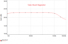
How does one interpret the graph?
Looking at the gain of the regulator's error amplifier by breaking the feedback loop and inserting a small a.c. voltage in the path.
I almost forgot… that the purpose of this exercise wasn't to build a GOOD regulator, but instead to build a TUBE regulator. Because strictly speaking, "regulation" is almost ideal for a solid state (and dâhmned simple) solution. A pair of emitter-followers, with each base "fed" by a pair of voltage-dividing resistors and a capacitor to cause each resistor-divider "supply" to be darn stable. Each HV transistor drops maybe 10% of raw HV (or more if you want). Each one in turn drops ripple by a large factor. hfe to be exact. 100 times nominally, or –40 dB. Just saying. 2 of 'em, and you get ripple drop of –80 dB.
No raised filaments requiring special consideration: namely separate winding(s) on the transformer. (Did someone already mention this?)
TIP 50-H … is a great candidate. Series current-limit resistors, and you're good to go. I've employed it (and have tubes of these little rascals) dozens of times, for just this purpose. +500 in, pre-regulated side. +470 at first stage. +440 at next stage. CRC primary filtering. 500 Ω series resistance between each stage. Stays within the transistor's max-amps rating(s) easily. Choosing the resistor-divider leveling caps also gives a "soft start" supply, which is kind of nice. RC is 1 sec time constant.
Anyway, before y'all squawk, I know this is the tubes section, and that the original poster(s) had a valve-based regulation circuit in mind.
So, please accept my proffered apologies.
Just saying, is all.
GoatGuy
Looking at the gain of the regulator's error amplifier by breaking the feedback loop and inserting a small a.c. voltage in the path.
Hi Jack,
Great, thank you! Well, 20 some odd db isn't all that amazing really. But I'm not sure it's the whole story is it? The error amp is feeding the EL84 which is also amplifying across the series resistor.
If I understand it correctly (capital IF), any ripple would be divided down by Rs and sensed by the error amp which would in turn feed it back to the EL84 to be further reduced by the inverted amplification across Rs. The Gm of the EL84 is the principle ripple rejection force and this Gm is being helped along by the dif amp.
So the ripple rejection 'gain' should be the gain of the dif amp multiplied by the Gm of the shunting tube, multiplied by Rs?
If we call the dif amp 20db, it's 10x voltage gain. That's multiplied by ~10 ma/v for 100ma/V or .1A/V "amplified transconductance." Multiplied by Rs of 2500, we get 250x "gain." That's a little closer to 50db rejection.
I could also be way off in the weeds somewhere.
50dB PSRR is rather uninspiring PSRR considering the effort involved.
At any rate, I get 17dB PSRR when the circuit is simmed with a 1V pk-pk perturbation. PSRR is very sensitive to parasitic L and C as well.
Will be happy to construct it, grandchildren's weekend demands notwithstanding.
At any rate, I get 17dB PSRR when the circuit is simmed with a 1V pk-pk perturbation. PSRR is very sensitive to parasitic L and C as well.
Will be happy to construct it, grandchildren's weekend demands notwithstanding.
Goat guy, raised filaments aren't required for a shunt regulator since the cathode is down by ground. A pass regulator, however, does.
Honestly, with a shunt regulator the error amplifier could be almost anything. A high gain bjt, opamp, or even an lm317.
Honestly, with a shunt regulator the error amplifier could be almost anything. A high gain bjt, opamp, or even an lm317.
I'm trying to figure out where all the gain is being lost. My best guess is an impedance mismatch between the 12ax7 'follower' and 12ax7 'grounded grid' that make up the two halves of the dif amp.
Zin on a grounded grid is Rk || (Ra + Rp) / (Mu + 1)
Zout on a follower is ~ Rp / Mu
So signal is divided down impedance match according to multiplier [Rk || (Ra+ Rp) / (Mu + 1)] / [Rp/Mu + Rk || (Ra+ Rp) / (Mu + 1)]
Looks like about 1,250 Zin, 650 Zout, so signal multiplier is 1250 / 1900 = 0.65 due to mismatch.
I'm not sure if the two halves of a dif amp can be separately treated in this way though.
Anyone else see where gain might be lost here?
I can't think of many other ways to do non-inverting amplification with two halves of a 12AX7. I suppose a grounded grid into a follower. Maybe a totem style with the input configured as a grounded grid (T Rex in original post uses cascode with grounded grid input).
Shunt Regulator EFFICIENCY
OK, that's true (filaments, raised, etc.)
I was thinking series regulator when I posted that.
However, correct me if I'm wring, but doesn't a shunt regulator also have two broad disadvantages: dissipating highest power under lowest (or no) downwind load, AND being quite load limited?
I say this because the "mental picture" is a resistor divider, where the upper resistor is a resistor, and the lower one is the error amplifier and primary shunting valve (or transistor, or 'almost anything'). that lower part is kind of a 'smart variable resistor' which serves to “adjust itself” instantaneously to be whatever “load” needed to maintain nearly-constant output. (I know, a childish view, but it serves.)
Assume for a minute that instead of it being just 1 dumb and 1 smart resistor, you're just talking about 2 resistors as a resistive voltage divider. Using Thevenin's rules,
k = R2 / (R1 + R2)
VO = k VI … and
ZO = k R1
Which is the equivalent circuit: (VO in series with ZO)
But where quiescent (zero load) power drawn is VI² / (R1 + R2)
Dunno. I 'get' why shunt regulation was used on color vacuum tube television CRTs, since the total current involved was μamp. Made sense in a hard-to-regulate situation. 40+ kilovolts. Need regulation without raised cathode voltage. Regulated device "nearly constant current" (being not just the accelerator, but also partially the recipient of the beam current.) Still, μamp. The flyback transformer would create whatever high voltage needed which without regulation would keep going up until something flashed over.
Is there a "silent assumption" that whatever stage is powered by these kinds of shunt regulators equally low-current and nearly constant power draws as well?
Seriously, just asking.
Of course, if you think of the driven stage(s) this way, then shunt regulation's power draw versus delivered power issue might not be so irksome.
GoatGuy
kylej₁₀₅₀;5001183 said:Goat guy, raised filaments aren't required for a shunt regulator since the cathode is down by ground. A pass regulator, however, does.
Honestly, with a shunt regulator the error amplifier could be almost anything. A high gain bjt, opamp, or even an lm317.
OK, that's true (filaments, raised, etc.)
I was thinking series regulator when I posted that.
However, correct me if I'm wring, but doesn't a shunt regulator also have two broad disadvantages: dissipating highest power under lowest (or no) downwind load, AND being quite load limited?
I say this because the "mental picture" is a resistor divider, where the upper resistor is a resistor, and the lower one is the error amplifier and primary shunting valve (or transistor, or 'almost anything'). that lower part is kind of a 'smart variable resistor' which serves to “adjust itself” instantaneously to be whatever “load” needed to maintain nearly-constant output. (I know, a childish view, but it serves.)
Assume for a minute that instead of it being just 1 dumb and 1 smart resistor, you're just talking about 2 resistors as a resistive voltage divider. Using Thevenin's rules,
k = R2 / (R1 + R2)
VO = k VI … and
ZO = k R1
Which is the equivalent circuit: (VO in series with ZO)
But where quiescent (zero load) power drawn is VI² / (R1 + R2)
Dunno. I 'get' why shunt regulation was used on color vacuum tube television CRTs, since the total current involved was μamp. Made sense in a hard-to-regulate situation. 40+ kilovolts. Need regulation without raised cathode voltage. Regulated device "nearly constant current" (being not just the accelerator, but also partially the recipient of the beam current.) Still, μamp. The flyback transformer would create whatever high voltage needed which without regulation would keep going up until something flashed over.
Is there a "silent assumption" that whatever stage is powered by these kinds of shunt regulators equally low-current and nearly constant power draws as well?
Seriously, just asking.
Of course, if you think of the driven stage(s) this way, then shunt regulation's power draw versus delivered power issue might not be so irksome.
GoatGuy
Last edited:
Honestly, with a shunt regulator the error amplifier could be almost anything. A high gain bjt, opamp, or even an lm317.
Oh I'm not in any way against SS in the reg. But I'd like to understand it with tubes first (because I know them better than SS) and then sub in SS parts where it makes sense.
The other interesting approach I've seen is sticking a TL431 in the cathode of the shunt tube and running the shunt as a grounded grid. It ends up just making the TL431-tube combination a hybrid device with the tube taking the high voltage and the TL431 determining conduction.
And I've got buckets of 12AX7s. I will someday find a use for them.
The shunt regulator, according to Walt Jung, separates the non-linear portions of the power supply from the audio amplification circuitry, while the series regulator is, well, in series. So your work would seem a worthwhile effort. I am loosely paraphrasing from his AudioXpress interview October, 2012 (archived on his site.)
you need a high-Z current source to feed the regulator. Salas HV uses DN2540 which will get into the meg-Ohm range. Avoid stray capacitance since this slams PSRR.
The Maida (series) should get you ~92dB of PSRR, but you can see the harmonics which this popular series regulator places back onto the supply rails.
This paper, an MSEE thesis from 1958, will make us all smarter: "The Design and Analysis of a Vacuum Tube D. C. Voltage Regulator Havin" by Charles Lamar Brantley Charles Lamar Bradley "The Design and Analysis of a Vacuum Tube D.C. Voltage Regulator" He uses a pentode (6AU6) and a 5751 diff amp.
Last edited:
OK, that's true (filaments, raised, etc.)
Is there a "silent assumption" that whatever stage is powered by these kinds of shunt regulators equally low-current and nearly constant power draws as well?
Yes, that's the conclusion I've come to when we want DC regulation (you could also use a shunt for simple AC ripple rejection which lessens the current requirements for the shunt but still requires the powered load to be a manageable impedance).
It's a balancing act between the load current and the Rs. The two are a parallel load with respect to the shunt tube. I think shunts like this are only intended for Class A loads. Series would be a better regulator where load current varies.
edit: Bless you, Jack. I'll check out that paper. The way you just described the Rs/Current source suddenly makes sense to me, too. We want this to be a high impedance because beyond dropping voltage from the input it is also functioning as a load for the shunt tube. Now I see what AJT was talking about with the MOSFET and Salas reg (originally I was thinking that was more of a series reg arrangement). I do have 10M45s laying around.
Last edited:
Two more ideas.
TubeCAD inspired w/ TL431 as control device:

Kevin Kennedy inspired w/ 12AX7 grounded grid cascode:

The former seems great for simplicity, but I'm still trying to use up my 12AX7s, hence the latter 🙂 CCS included for both according to AJT's and Jack's insight (which I eventually understood after multiple proddings).
The cascode would have pretty low input impedance: Rk || (Rp + Ra) / (Mu + 1), but the source impedance should be pretty low as well, shouldn't it? The poor PSRR of the cascode is actually not a bad thing here (pointed out by JB) because we're trying to amplify power supply noise anyways.
According to the great and powerful Merlin's website, Zout of the cascode is going to be roughly the load resistor's value. Input impedance of the shunt tube is 300k based on the resistor divider from output voltage.
Haven't worked with cascodes before (or grounded grid), so time to dig up Kevin Kennedy's series reg for inspiration (also uses 12AX7 cascode) and bone up on Merlin and JB articles.
TubeCAD inspired w/ TL431 as control device:
Kevin Kennedy inspired w/ 12AX7 grounded grid cascode:
The former seems great for simplicity, but I'm still trying to use up my 12AX7s, hence the latter 🙂 CCS included for both according to AJT's and Jack's insight (which I eventually understood after multiple proddings).
The cascode would have pretty low input impedance: Rk || (Rp + Ra) / (Mu + 1), but the source impedance should be pretty low as well, shouldn't it? The poor PSRR of the cascode is actually not a bad thing here (pointed out by JB) because we're trying to amplify power supply noise anyways.
According to the great and powerful Merlin's website, Zout of the cascode is going to be roughly the load resistor's value. Input impedance of the shunt tube is 300k based on the resistor divider from output voltage.
Haven't worked with cascodes before (or grounded grid), so time to dig up Kevin Kennedy's series reg for inspiration (also uses 12AX7 cascode) and bone up on Merlin and JB articles.
Hmm, 12AX7 cascode does not look pretty at all with only 250V. Looks slightly better fed from the other side of the CCS @ 350V B+, but output impedance is not going to be a good match with the 300k input impedance of the EL84.
Might work as AC shunt regulator (1M grid resistor on regular cathode biased EL84), but then I'm injecting pre-reg noise into the cascode output (in-phase) via the bad PSRR. Seems like that could cause the shunt to 'over correct.'
Might work as AC shunt regulator (1M grid resistor on regular cathode biased EL84), but then I'm injecting pre-reg noise into the cascode output (in-phase) via the bad PSRR. Seems like that could cause the shunt to 'over correct.'
I've got the shunt sickness.
Here's an AC shunt with a cascode before the CCS:

The load on the cascode is calculated to be equal to the lower RP + (Mu+1)*Rk. According to JB, this makes the gain of the upper grid 1. So the cap across the upper section of the bias divider injects power supply noise, which is inverted at the anode by a gain of 1. In theory that cancels the power ripple (at the output of the cascode). The ripple on the output after the shunt is fed to the grounded grid lower triode and so appears non-inverted as the error signal on the upper anode and is fed to the shunt device. The EL84 is configured as non fixed bias (mostly to get the input impedance up to a manageable level for the cascode). So this will vary with wall voltage, but should shunt noise and ripple.
Here's a boring old grounded grid feeding a CF to better drive the low input impedance of a DC shunt EL84:

I wonder if judicious choice of voltage reference would make it possible to completely direct couple this arrangement.
Most values aren't calculated above, so I don't know how feasible the ideas are yet.
Here's an AC shunt with a cascode before the CCS:
The load on the cascode is calculated to be equal to the lower RP + (Mu+1)*Rk. According to JB, this makes the gain of the upper grid 1. So the cap across the upper section of the bias divider injects power supply noise, which is inverted at the anode by a gain of 1. In theory that cancels the power ripple (at the output of the cascode). The ripple on the output after the shunt is fed to the grounded grid lower triode and so appears non-inverted as the error signal on the upper anode and is fed to the shunt device. The EL84 is configured as non fixed bias (mostly to get the input impedance up to a manageable level for the cascode). So this will vary with wall voltage, but should shunt noise and ripple.
Here's a boring old grounded grid feeding a CF to better drive the low input impedance of a DC shunt EL84:
I wonder if judicious choice of voltage reference would make it possible to completely direct couple this arrangement.
Most values aren't calculated above, so I don't know how feasible the ideas are yet.
Attachments
Any particular reason to have the EL84 triode strapped? If the regulator is working properly there should be clean screen power. Also, in your DC shunt regulator it isn't really DC. The EL84 will self-bias and the 12AX7 doesn't have any DC control over it and is only amplifying ripple. Should the load disappear from that it will not maintain 250VDC.
Last edited:
Hi Kyle,
I'm using triodes just because that's what I'm more familiar with and so it's easier for me to get a feel for shunt regulators that way.
Regarding 'DC' regulation, that's a good point. Originally I was using a series resistor rather than a CCS. With the CCS, I don't think it will work quite the same way.
The cathode voltage is fixed with the zener and the grid is biased by a divider from the output, so if the output voltage increases, the grid will become less negative relative to the cathode. With a series resistor, the tube would conduct more because of the decreased bias, which would drop more voltage across the resistor, which would bring the output back down.
With a CCS, if the output voltage increases and the grid becomes less negative relative to the cathode, the tube will drop fewer volts (because the current is fixed) and so attempt to pull the output down. At least that's how I'm interpreting it based on plate curves.
I hadn't thought of this and I may still not be fully wrapping my head around it. Thank you for pointing it out!
Edit: the current source symbol is what I'm using for CCS because I couldn't find the usual CCS symbol in the software I'm using, BTW. Bad terminology on my part.
Last edited:
Thanks, Merlin el Mago! You can read about my misadventures with series regulators here:
http://www.diyaudio.com/forums/tubes-valves/294797-can-we-talk-about-series-pass-regulators.html
I did build one and am very happy with it. Just trying to learn about shunt regulators to continue my education.
- Status
- Not open for further replies.
- Home
- Amplifiers
- Tubes / Valves
- Can we talk about tube shunt regulators?