Note in terms of voltage references you should look at the 5651, 85A1 and 85A2 - all can be run on the output side in what looks like constant current operation, and require only 3mA for good regulation - which is much better than the 0C3 which is a regulator tube, not a reference.
These tubes are all quite cheap on eBay, don't buy used ones.
These tubes are all quite cheap on eBay, don't buy used ones.
One interesting regulator circuit is described in "Valley and Wallman, Vacuum tube amplifiers" in the section on "Direct coupled amplifiers" in my edition it is Fig 11.58 "Voltage regulator employing positive feedback" It is a circuit with both positive and negative feedback making it possible to achieve very low output impedance and therefore very good load regulation. It is even possible to adjust it to give negative output impedance, (Voltage increases with higher current draw). I have built this many years ago just for fun and it worked well, I used a 5651 reference driven from the output side. Series tubes where 2 parallel coupled 807 and the double triode 6SL7. The voltage is constant for a large range of current but it need a bleeder on the output if it should also handle very low load currents.
The one comment I have about the long tailed pair is limited gain...
Yes, the overall performance would be essentially better with a single pentode error amplifier.
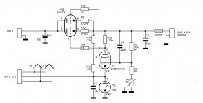
Something like this:
Attachments
One interesting regulator circuit is described in "Valley and Wallman, Vacuum tube amplifiers" in the section on "Direct coupled amplifiers" in my edition it is Fig 11.58
Thanks, tubetvr! I found a copy of this on Pearl Hifi:
Careful, link is to a huge PDF
Regarding the tube choice (kevinkr and artosalo), I understand that a pentode is a better choice (higher gain) and that there are lower current voltage references (0C3 runs at 11.5mA so I could save a few mA). I do have some 9 pin pentodes (12BY7A, 6JC6A, 6CL6) that might be handy.
I've also seen the 12AX7 frequently used in cascode for this application (especially kevinkr's design).
For the moment I'm trying to limit my choices to mostly parts on hand and (somewhat) familiar topologies. I'm not at all against looking at different styles, I'm just trying to understand the series pass regulator in the process (and I find it easiest to picture 'regular' grounded cathode arrangements).
It's a good place to start and a good way to learn, as I pointed out it's where I started. I think it is great that you are exploring the issue at all - so many people dismiss tube based regulators without even giving them a try.
Getting going with parts on hand is a viable approach.
The 12AX7A is far from ideal as a cascode, but it's ubiquitous and will provide sufficient gain for good results which is why I choose it. Other types that can work well are the 12AT7A and 6DJ8 (within it's voltage limitations). I've also used 6J9P and D3A as pentode error amps in other designs and generally prefer the cascode, but at higher voltages an HV pentode would definitely be a winner.
I would change the 1K resistor from the gas tube back to 100K and add a cap to ground to create an LPF for the reference tube noise.
Like this?

BTW, I think I can increase the cap value across the 0C3 to 0.1uF (couldn't remember what the maximum recommended value when I was throwing the initial schematic together).
The 12AX7A is far from ideal as a cascode, but it's ubiquitous and will provide sufficient gain for good results which is why I choose it. Other types that can work well are the 12AT7A and 6DJ8 (within it's voltage limitations).
Thanks for your encouragement, kevinkr! I've wondered exactly that about the 12AX7 in cascode (my limited understanding being that cascodes are driven by transconductance). I do have nearly as many 12AT7s as 12AX7s.
I'm planning on having a separate heater transformer specifically for the regulator circuit and biasing it to approximately 1/2 the output. With a cascode I'd have to be much more careful with Vhk. 6AS7 gives me lots of room but I'll have to learn up on the cascode to see if there's a suitable range that won't violate the maximum allowed for one of the two halves.
Yes, like that.. I would however make that 10uF more like 0.47uF.
Also I would not place a 0.1uF across the 0C3 as that is right around the range where the combination becomes a relaxation oscillator. The most I would recommend is 0.047uF and your choice of 0.01uF is reasonable for HF noise suppression. The 100K/0.47uF LPF will take care of most of the noise.
Also I would not place a 0.1uF across the 0C3 as that is right around the range where the combination becomes a relaxation oscillator. The most I would recommend is 0.047uF and your choice of 0.01uF is reasonable for HF noise suppression. The 100K/0.47uF LPF will take care of most of the noise.
Any progress on this regulator?
Anyway as others have indicated, a single pentode amplifier will give a larger open loop gain than the LTP arrangement.
Anyway as others have indicated, a single pentode amplifier will give a larger open loop gain than the LTP arrangement.

Excellent, and congratulations! Follow your path and figure out what works best with the parts you have on hand.
How about some more pictures? (Internal)
How about some more pictures? (Internal)
I'm out of town at the moment but I'll snap more pics and share. Thanks again for your help in making it a reality!!

Pretty tidy. Have you referenced the filament supply to the pass tube and error amplifier to some appropriate well filtered DC voltage level? This will assure that the filament to cathode insulation does not fail over time. (Above the cathode voltage present on the error amp and below the voltage on the pass tube cathode such that neither maximum is violated - otherwise a separate winding is required. I can see they currently share a winding)
Hi Kevin,
Yep, the power supply heaters are referenced to 1/2 B+ output. The actual heater supply for the amp connected is referenced to 1/6th B+ (IIRC). Between about 250V and 400V output (depending on current draw) seems fairly safe with regards to the 6AS7's perveance and dissipation.
Here's everything altogether:

The amp is just a really simple choke loaded 12BH7A cap coupled to a triode strapped 6L6/6V6/EL34 (adjustable voltage comes in handy here). I plan on using the amp as a bit of a test bed for various output tubes and ideas.
Initially I tried a direct coupled arrangement (hence the chokes) but ended up with a bunch of distortion (I think my LEDs were dropping too much volts for the input and driving it to cutoff). I just whipped up the simpler cap coupled amp so I could listen to the power supply 🙂 That said, it does sound pretty darn good so far.
Yep, the power supply heaters are referenced to 1/2 B+ output. The actual heater supply for the amp connected is referenced to 1/6th B+ (IIRC). Between about 250V and 400V output (depending on current draw) seems fairly safe with regards to the 6AS7's perveance and dissipation.
Here's everything altogether:
The amp is just a really simple choke loaded 12BH7A cap coupled to a triode strapped 6L6/6V6/EL34 (adjustable voltage comes in handy here). I plan on using the amp as a bit of a test bed for various output tubes and ideas.
Initially I tried a direct coupled arrangement (hence the chokes) but ended up with a bunch of distortion (I think my LEDs were dropping too much volts for the input and driving it to cutoff). I just whipped up the simpler cap coupled amp so I could listen to the power supply 🙂 That said, it does sound pretty darn good so far.
One interesting regulator circuit is described in "Valley and Wallman, Vacuum tube amplifiers" in the section on "Direct coupled amplifiers" in my edition it is Fig 11.58 "Voltage regulator employing positive feedback" It is a circuit with both positive and negative feedback making it possible to achieve very low output impedance and therefore very good load regulation. It is even possible to adjust it to give negative output impedance, (Voltage increases with higher current draw). I have built this many years ago just for fun and it worked well, I used a 5651 reference driven from the output side. Series tubes where 2 parallel coupled 807 and the double triode 6SL7. The voltage is constant for a large range of current but it need a bleeder on the output if it should also handle very low load currents.
Attachments
- Home
- Amplifiers
- Tubes / Valves
- Can we talk about series/pass regulators?