larryB: What do you mean by "pure sine", % of THD+N? The output transformer will be extremely expensive! I suggest you put the isolation on supply source side and design an active-balanced output stage. E
No, I really meant with isolation, thus floating.Unless you need the isolation.
larryB: We still do not know what you wold like to accomplish.
To answer one Q: a floating output can allways be grounded, but you can not float a grounded (single ended) output (oh, my head hurts!). Think of it as a balanced (floating) line and an unbalanced (grounded) line.
Hi Mikey, of course you can float the secondary of a transformer, it is not referenced to anything - in the real world its called isolation transformer. The single ended amplifier driving its primary has nothing to do with what you want to connet to the secondary.
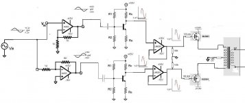
So does my new design have any mistakes , do I understand everything ?
Is there somethign wrong with the op amp and power mosfet following the same power line ( transformer primary ) , it seems like this would be more inductance on the line but after the capacitance (mosfet) . I was originally under the impression that the op amp needed extra short leads and share the power line as short as possible with the mosfet . I hear these mosfets are "capricious" but they have too much advantages besides that .
What if I had my feedback lead of the amp on the source of the mosfet , I dont even dare try that lol .
Ok so I believe I found a better op amp , the lm7322 , It seems like the right choice and small/cheap .
LM7322 - Dual Rail-to-Rail Input/Output, ±15V, High Output Current and Unlimited Capacitive Load Operational Amplifier±15V, High Output Current and Unlimited Capacitive Load Operational Amplifier
Attachments
Last edited:
You claim you want a clean sine output.
Yet you deliberately dirt it up with a BJT-stage and mosfets and a transformer.
At least the BJT stage is absolutely unnessecary in my opinion, as the OpAmps would provide enough voltage gain if you let them. So you could at least get rid of the BJT-Stage and the second opamp (the voltage follower).
If you really, really want to use a transformer at the output you could use a (integrated) poweramplifier (such as the already mentioned LM3886). Use one of them with a transformer in single ended operation. i.e. one primary winding with no taps, one end of the winding tied to ground, the other tied to the amp.
Maybe with some resistance added so the Amp is not running into a DC short, and actually that's where the unnessecary trouble starts again, which you could have avoided, if you had omitted the xformer in the first place.
otherwise I can only recommend you to build it (or simulate it 😉 ) to see what will happen, and learn from mistakes
Hi ,
The bjt stage is simple and I understand it lol , its what I tought would be a simplest way to just bias a sine wave and then buffer that with a fast op amp , it costs very little space and about 2$ , an output transformer costs like 30$ .
I like the zeus amplifier for my application , nothing is better for my application , I found that out after reading the whole internet , as for the price of the output transformer I dont care .
I dont need 100% pure sine , I can accept 99% .
Last edited:
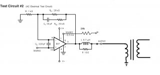
an audio transformer is no more a DC short than a speaker voice coil, so it's not a problem with the LM3886.
save yourself the trouble of using the op amps and transistor stages and use an LM3886 feeding a transformer. the LM3886 is an op amp capable of about 60W output with better than 1%THD (which satisfies your requirement for a "99% pure" sine wave).
save yourself the trouble of using the op amps and transistor stages and use an LM3886 feeding a transformer. the LM3886 is an op amp capable of about 60W output with better than 1%THD (which satisfies your requirement for a "99% pure" sine wave).
Attachments
Thx for the help unclejed , I am back to my hobby even if im tired , must research more on driving this zeus using solid state . Its too frikkin expensive this thing .
If anyone has a better idea on how to drive the zeus output without the input transformer that would be really great .
I dont see this happening with a transformer , I could blow my amps with transcients , I am not using clamps or freewheels nowhere . I already tried such a design , altho it looks like the easy answer and gives out ac its not durable .
I like the zeus for that , durable transistors and class a contiuous conduction with no commutation , I just keep it cool and thats that . Gotta thx Ms Parker for making this .
Basicly my most important key is durability without too much complexity . After speaking to the people from class d I know lateral fet is the way to go .
Last edited:
LM3886's are pretty durable devices, and don't need anywhere near the same amount of heat sinking that Class A needs. you said you're driving a 35 ohm load with the transformer secondary?
maybe if you give a clearer description of what you're trying to accomplish...
maybe if you give a clearer description of what you're trying to accomplish...
- Status
- Not open for further replies.
- Home
- Amplifiers
- Solid State
- Can this work ?